 FEXLINK Research Institute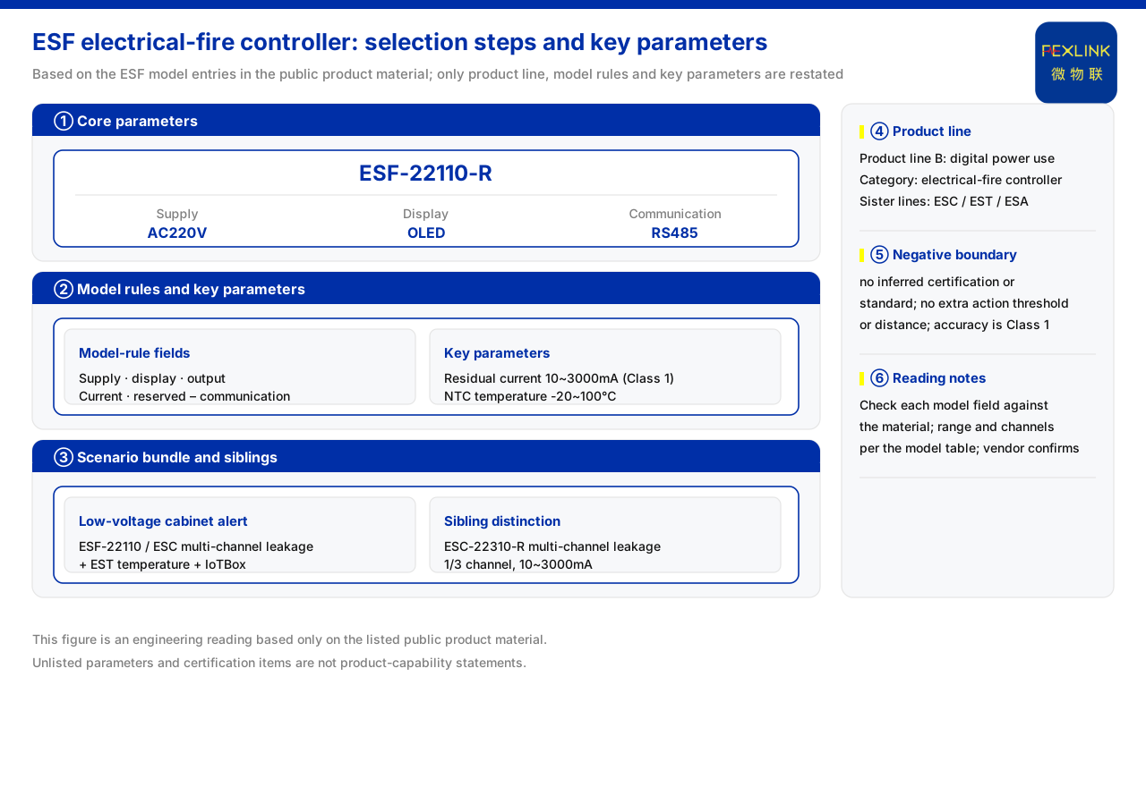
Direct answer
Selection for electrical fire monitoring can be broken into a sequence from the monitored quantity to the packaged combination: first determine the electrical quantities to monitor, then work through supply, display, output, and current parameters according to the model rule, then verify the key parameters, and finally choose the packaged combination by application scenario. The materials place the electrical fire monitoring and control device in the digital power-consumption and electrical-safety monitoring product line, with a model rule that orders supply, display, output, current parameters, and a reserved field, and communication as a separate segment. Following this line narrows the choice step by step from what to measure to which model to pick, rather than stopping at the generic category level.
1. Step one: clarify the monitoring object
Electrical fire early warning usually takes residual current and temperature as its basic monitoring quantities. In the listed models, residual current is 1 channel and temperature is 4 channels, and the same model provides digital inputs and a relay output. This shows that one controller can acquire both residual current and temperature and use the result for local control. The first selection step should confirm the monitoring quantities and channel counts the site needs to cover, then judge whether a single unit suffices. If there are more monitoring points, an extended model such as a multi-channel leakage-current monitoring and control device should be considered.
2. Step two: break down the fields by the model rule
The materials give the model rule fields as supply, display, output, current parameters, and reserved, with communication as a separate segment. The current-parameter field lists settings of 10~3000 mA and 5 A/0.5 mA. Expanding the rule, the selector need only answer item by item: what the site supply is, whether local display is needed, what output is required, and which current-parameter setting is the target. Because a reserved field exists, the model rule itself signals that some combinations may not yet be open, so the listed models should be the boundary and fields should not be assembled on one's own.
3. Step three: compare the listed models' differences
The two listed models illustrate the difference in supply and output. One uses an AC supply and provides display, 1 residual-current channel, 4 temperature channels, digital inputs, and a relay output, with RS485 communication; the other uses a low-voltage DC supply and likewise provides display, 1 residual-current channel, and 4 temperature channels, with a relay output and RS485, but the materials do not list digital inputs. The two agree on display, residual-current channels, and temperature channels, differing mainly in supply and digital inputs. If the site has only a low-voltage DC source, the DC model should be preferred; if external digital inputs must be connected, whether the corresponding input exists should be checked.
4. Step four: verify the key parameters
After the candidate model is fixed, the key parameters need one more check. The materials record that the residual-current range is 10~3000 mA with accuracy class 1; temperature uses NTC measurement over -20~100 °C with an accuracy of ±1 °C and an external wire length of 1 m; and the relay contact capacity is AC 250 V 3 A and DC 30 V 3 A. These parameters decide whether the controller can cover the site's range requirements and whether the relay can directly drive the controlled circuit. Selection cannot look only at the model fields; these parameters must be compared item by item with the field conditions.
5. Step five: multi-channel leakage and the packaged combination
When monitoring points exceed a single unit's coverage, the materials provide a multi-channel leakage-current monitoring and control device that offers 1 or 3 channels of leakage monitoring, a leakage range of 10~3000 mA with accuracy class 1, and RS485 communication. It extends residual-current monitoring to multiple channels, suiting cabinets with many circuits. On the packaged side, the recommended combination for the low-voltage distribution-cabinet electrical fire early-warning scenario is an electrical fire controller or a multi-channel leakage controller, with temperature monitoring and an IoT gateway. The last step of selection is therefore not choosing one device but fitting monitoring, temperature measurement, and networking together by scenario.
6. Step summary and common misreadings
Connecting the five steps: clarify the monitoring object and channel counts, locate each field by the model rule, compare the listed models' differences, verify the key parameters, and finally complete the packaged combination by scenario. Each step rests on the materials, and the conclusion of one step becomes the input of the next. Two common misreadings should be avoided: treating the reserved field of the model rule as a freely combinable slot, when the listed models are in fact the boundary; and looking only at residual current while ignoring temperature channel count and relay capacity, so that the controller can measure but cannot meet the site's interlock requirements.
7. Landing the steps on scenario and interlock
The selection steps must finally land on a scenario. The recommended combination for the low-voltage distribution-cabinet electrical fire early-warning scenario shows that a single controller is only the starting point: residual current and temperature are acquired by the controller, temperature monitoring can be supplemented by a multi-channel temperature intelligent controller, and the data goes up through an IoT gateway. If the scenario has many circuits, a multi-channel leakage-current monitoring and control device can replace or supplement the single-channel residual-current monitoring. The first four steps therefore select the device, the fifth fits it into a package, and a mature approach reads the two together: fix the device by monitoring object and range, then decide whether multi-channel models and temperature supplementation are needed by circuit count and interlock requirements, and finally fit device, temperature measurement, and networking together by scenario. The result then contains both the model and its place in the system.
8. What evidence a selection record should retain
After selection, it is advisable to record the basis for review. The first item is the monitoring object and channel counts: how many residual-current channels, how many temperature channels, and whether digital inputs are needed. The second is the value of each model-rule field, including supply, display, output, and current-parameter setting, with the field condition noted. The third is the key-parameter check, including residual-current range and accuracy, temperature range and wire length, and relay capacity. The fourth is the packaged combination, namely whether a multi-channel leakage controller, temperature monitoring, and an IoT gateway are configured. With these written clearly, the result is no longer just a few models but a traceable judgment. Because the materials give no protection settings, no threshold beyond the materials should be added to the record.
Scope and limitations
First, this article explains only the selection steps for electrical fire monitoring, and the factual boundary is limited to the model rule, models, key parameters, and scenario combination listed in the materials; it introduces no unlisted standard clause, certification, or engineering code.
Second, the materials give no quantitative correspondence between residual-current threshold, operating time, and protected object; the steps in the text are a general selection order induced from the listed fields and models and do not constitute protection-setting design.
Third, the range, temperature, and relay parameters are those already recorded in the materials; this article does not infer the specifications of unlisted models from them, nor does it infer performance or effects.
Fourth, a specific selection must be confirmed against the number of field circuits, supply conditions, and interlock requirements; this article provides no setting calculation or configuration list.