 FEXLINK Research Institute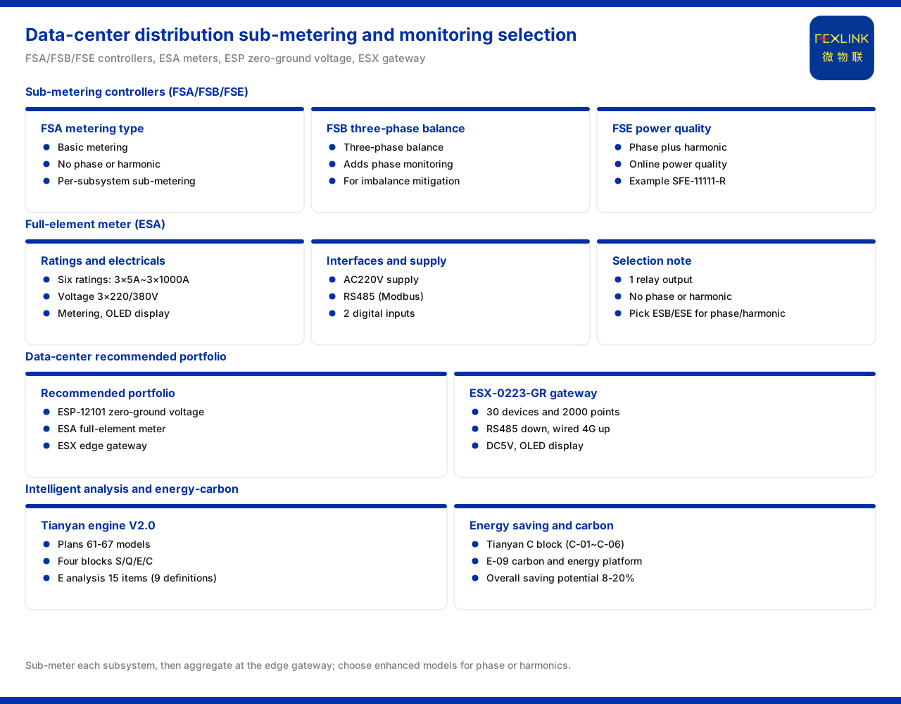
Direct answer
When a data centre's PUE stays high, the first step is not to rush into replacing equipment but to break "where the power goes" down by subsystem. The path the product knowledge base gives is sub-metering: measure separately on the IT, cooling, distribution and lighting circuits with multi-parameter electrical intelligent controllers and all-parameter smart meters, then consolidate and upload through edge gateways, on which basis the platform side calculates and locates the high-share subsystems and finally produces a rankable energy-saving retrofit list with energy-use analysis and carbon management. The product knowledge base also records that the recommended combination for data-centre neutral-to-ground voltage and distribution monitoring is the neutral-to-ground voltage monitor (ESP-12101-R), the all-parameter smart meter and the intelligent edge-computing gateway (ESX-0223-GR); in energy saving and carbon management, it recommends the Tianyan engine C block, the carbon-accounting model and the smart energy-carbon IoT platform, whose quantified value basis includes a composite energy-saving potential of 8% to 20%. The following expands item by item.
Sub-metering: first break down "where the power goes"
Faced with the problem that how much cooling, distribution and IT each account for cannot be stated, sub-metering is the common premise. The product knowledge base maps this need onto multi-loop meters and controllers: install metering devices separately on the key circuits and aggregate energy consumption by subsystem, so the share of each can be compared and ranked.
Sub-metering in a data centre differs from ordinary distribution in adding a layer of neutral-to-ground voltage monitoring. The product knowledge base lists data-centre neutral-to-ground voltage and distribution monitoring as a separate typical scenario, showing that sub-metering here is not merely counting by loop but must also cover monitoring of a specific electrical quantity. Only by combining these two needs in one chain can both "where it is used" and "whether it is safe" be answered.
The difference among the three multi-parameter electrical intelligent controllers
The product knowledge base records that the multi-parameter electrical intelligent controllers come in three versions, FSA, FSB and FSE, with 12 current specifications in total and two networking modes. The three differ in monitoring depth: FSA, the meter type, is basic meter monitoring, excluding phase and harmonics; FSB, the three-phase balance type, adds phase monitoring; and FSE, the power quality type, adds harmonic monitoring on top of phase monitoring, with a model such as SFE-11111-R.
The functions common to the three include an OLED display, one residual-current channel, voltage 3×220/380V, four temperature monitoring channels, two digital inputs, two relay outputs, meter monitoring and two RS485 ports (Modbus). The current specifications cover six tiers: 3×5A, 3×100A, 3×200A, 3×400A, 3×600A and 3×1000A. In selection, first determine the circuit's current magnitude, then decide the version by whether phase and harmonics are needed.
The "12 current specifications" comes from the combined count of the three versions' own specifications, while the six tiers are the magnitude coverage common to the whole series. This article restates the product knowledge base as it stands and does not infer how the specific specification combinations are formed.
All-parameter smart meter and neutral-to-ground voltage monitoring
Besides the controllers, the product knowledge base also lists the all-parameter smart meter, whose models cover six tiers from ESA-22111-R to ESA-22161-R, with current specifications identical to the six tiers above. The whole series has voltage 3×220/380V, supports meter monitoring, has two digital inputs and one relay output, is powered by AC220V, and offers OLED and RS485 (Modbus); this version excludes phase and harmonic monitoring, and if phase or harmonics are needed the three-phase imbalance monitor or the power-quality monitor of the same architecture should be chosen instead.
In the data-centre scenario, the recommended combination the product knowledge base gives is the neutral-to-ground voltage monitor (ESP-12101-R), the all-parameter smart meter and the intelligent edge-computing gateway. The monitor handles the data-centre-specific neutral-to-ground voltage need, the smart meter handles sub-metering, and the two converge into the gateway for upload. This shows that sub-metering is not a single product but a pairing of metering, monitoring and consolidation.
The division of labour between the controllers and the meter is thereby clear: branch circuits needing phase and harmonics take the corresponding controller version, those needing only meter monitoring can use the all-parameter smart meter, and the neutral-to-ground voltage is handled separately by the dedicated monitor. Dispatching products by the nature of the circuit is closer to sub-metering reality than applying one model across the whole line.
Edge consolidation: 30 devices and 2000 data points
Metering data needs to be consolidated. The product knowledge base records that the intelligent edge-computing gateway (ESX-0223-GR) has an access capability of 30 devices and 2000 data points, with RS485 downstream and wired plus 4G upstream. The same capability also appears on the industrial gateways (CW-C1, CW-C2 and CW-C3) and the industrial wearables (CX-08R06AI08-C1, CX-08R06AI08-C2 and CX-08R06AI08-C3).
Under the convention of 30 devices and 2000 data points, if sub-metering is spread out by circuit, the number of gateways and the scale of data points must be accounted for at the layout stage, so the upstream channel is not insufficient after metering points increase. Only by linking this layer with the meters and controllers of the perception layer will sub-metered data have the conditions for stable upload.
This article only restates the gateway's access scale and communication mode, not its computing power, storage or breakpoint-resume capability.
Platform side: how energy analysis points to PUE
After the data is aggregated, platform-side models are needed to turn shares into conclusions. The product knowledge base records that the Tianyan engine V2.0 plans 61 to 67 models across four blocks, S, Q, E and C; of these, the E energy-use analysis block has 15 items (9 under the document's stated convention), the P0 launch model is E-01, using non-intrusive load disaggregation. There are also 17 special topics, including data-centre power-supply reliability.
For the PUE problem, the value of energy-use analysis lies in breaking the total down to device and circuit level: first obtain each subsystem's energy use by sub-metering, then use energy-use analysis to identify composition and change, locating the highest-share subsystem most worth prioritising for retrofit. This article only restates the model blocks and launch direction, not their disaggregation accuracy.
Selection combination and value basis for energy saving and carbon management
After locating the high-share subsystem, the energy-saving and carbon-management direction likewise has a combination. The product knowledge base records that this direction recommends the Tianyan engine C block (C-01 to C-06), the carbon-accounting model E-09 and the smart energy-carbon IoT platform. The C block handles energy-saving analysis, the carbon-accounting model handles carbon-emission accounting, and the platform carries the data and results.
On the value basis, the product knowledge base records that the Taiyi intelligent control hub system has a composite energy-saving potential of 8% to 20%, with applicable industries including data centres. This interval is the knowledge base's convention, and this article does not commit to the energy-saving ratio of any specific data centre on its basis; it shows only that a checkable quantified potential exists between sub-metering and retrofit.
Implementation sequence for sub-metering
First, divide metering circuits by subsystem (IT, cooling, distribution, lighting and so on) and determine the current magnitude of each circuit. Second, choose the controller version by monitoring depth: the meter type for meter monitoring only, the three-phase balance type when phase is needed, the power quality type when harmonics are needed; or use the all-parameter smart meter on branch circuits. Third, install the neutral-to-ground voltage monitor where the data centre has a neutral-to-ground voltage need. Fourth, configure the intelligent edge-computing gateway under the access convention of 30 devices and 2000 data points, and check its RS485 downstream and wired plus 4G upstream communication. Fifth, enable energy-use analysis on the platform side and form a retrofit-priority list with the energy-saving and carbon-management combination.
Applicability and limits
- This article is limited to the product knowledge base's existing statements on the multi-parameter electrical intelligent controllers, the all-parameter smart meter, the neutral-to-ground voltage monitor, the intelligent edge-computing gateway, and energy saving and carbon management, and does not extend to unlisted parameters, certifications or cases.
- The differences, common features and current specifications of the three controllers are cited as they stand in the product knowledge base; the model tiers, voltage, channel counts and supply of the all-parameter smart meter are likewise limited to the material.
- The intelligent edge-computing gateway's 30 devices and 2000 data points and its communication mode follow the product knowledge base convention; the same convention for the industrial gateways and industrial wearables is given for parallel reference only.
- The Tianyan engine V2.0's model-count interval, the number of E energy-use analysis items and the launch direction, the number of special topics, and the composite energy-saving potential of 8% to 20% are all product knowledge base conventions; this article does not infer specific project effects.
- This article does not constitute a commitment to any unlisted indicator; actual capability is subject to the latest product documentation and project scheme.