 FEXLINK Research Institute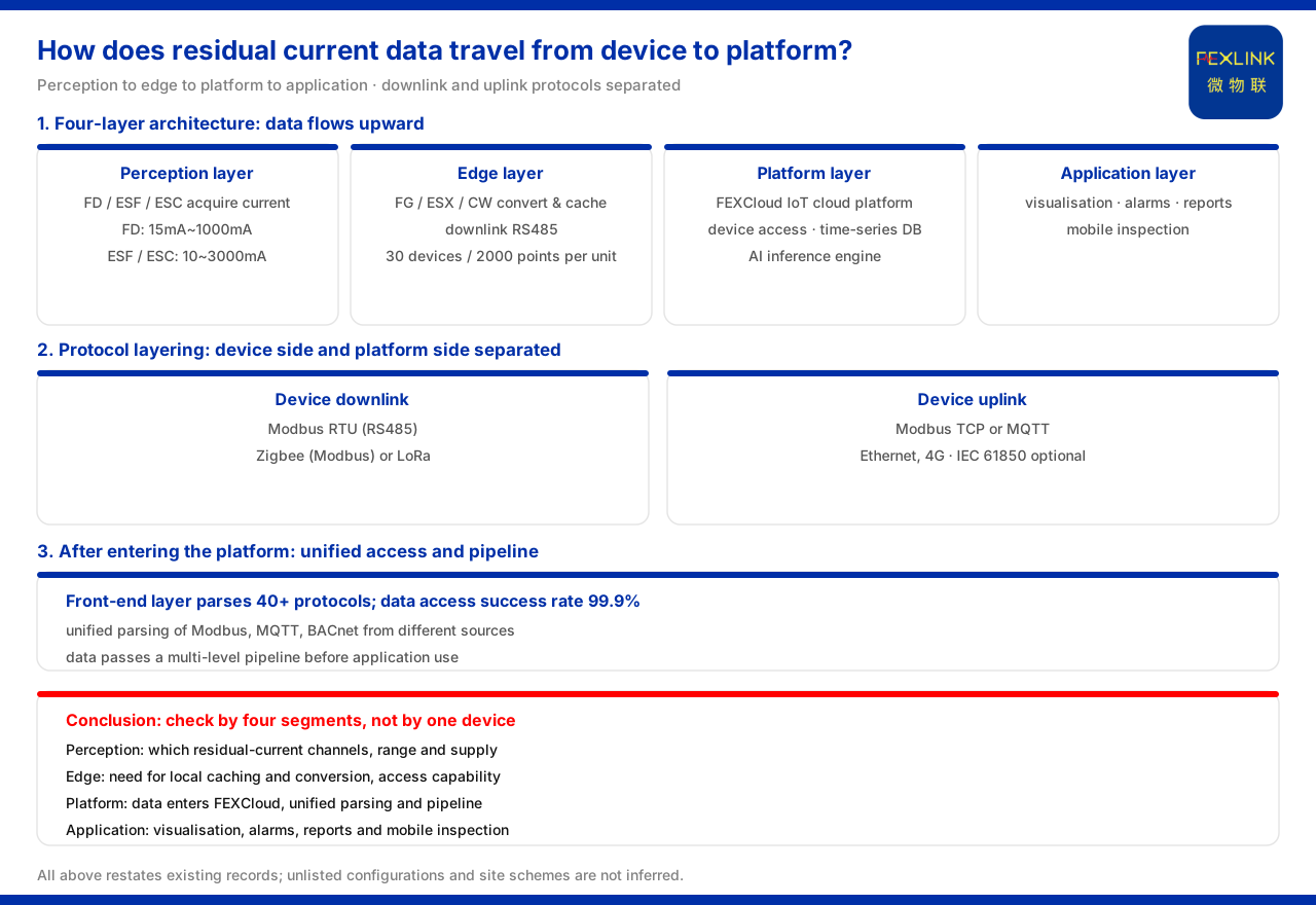
Direct answer
Residual current data travels from the device to the platform along the four-layer architecture defined by the product knowledge base: perception-layer acquisition, edge-layer conversion and caching, platform-layer access and processing, and application-layer presentation. The perception layer turns the on-site residual current quantity into uploadable data through residual-current / leakage monitoring products such as the FD mains residual-current monitoring module (e.g. FD-01011-R), the ESF electrical fire monitoring & control device (e.g. ESF-22110-R) and the ESC multi-channel leakage-current monitoring & control device (e.g. ESC-22111-R); the edge layer, carried by the FG lightning-protection smart gateway (e.g. FG-0221-ER), the ESX intelligent edge-computing gateway (e.g. ESX-0223-GR) and the CW industrial gateway (e.g. CW-C1), performs protocol conversion, edge computing and local caching; the platform layer is the FEXCloud IoT cloud platform; and the application layer provides visualisation, alarms, reports and mobile inspection. In protocol terms, the device downlink uses Modbus RTU (RS485), Zigbee (Modbus) or LoRa, and the device uplink uses Modbus TCP or MQTT (Ethernet, 4G), with IEC 61850 optional at gateway level. The key to understanding this path is to separate the four segments of "acquisition—conversion—access—presentation" rather than looking only at one device or one protocol.
1. The four-layer architecture from device to platform
The product knowledge base defines the monitoring system as a general four-layer architecture. The perception layer acquires data from monitoring modules, smart meters and sensors, and on the sensor side includes Rogowski coils, NTCs and microampere-level leakage-current sensors; the edge layer contains the lightning-protection smart gateway, the intelligent edge-computing gateway and the industrial gateway, as well as the industrial wearable and the cloud PLC (with expansion modules), performing protocol conversion, edge computing and local caching; the platform layer is the FEXCloud IoT cloud platform, taking on device access, a time-series database and an AI inference engine; and the application layer presents visualisation, alarm management, analytical reports and mobile inspection. Residual current data flows up along exactly these four layers: acquired at the perception layer, converted and cached at the edge layer, and finally entering the platform layer for the application layer to use. Splitting the path into these four layers is what allows each segment's problem to be located.
2. Perception layer: where residual current is acquired
The acquisition of residual current falls on several perception-layer products. The product knowledge base records that the FD mains residual-current monitoring module (e.g. FD-01011-R) provides 1 residual-current channel with an acquisition range of 15mA to 1000mA, supplied at DC12V and communicating over RS485. The ESF electrical fire monitoring & control device (e.g. ESF-22110-R and ESF-12110-R) has 1 residual-current channel (10mA to 3000mA, accuracy class 1), 4 temperature channels, an OLED display and RS485 communication, and includes digital inputs and relay outputs. The ESC multi-channel leakage-current monitoring & control device provides 1 or 3 leakage-current channels (leakage 10mA to 3000mA, accuracy class 1), supplied at AC220V or DC5V and communicating over RS485. The three differ in channel count and element coverage: single channel, single channel plus temperature, or multi-channel leakage. The data is produced at this layer, with RS485 as the factory specification.
3. Edge layer: protocol conversion and local caching
After leaving the perception layer, the data first enters the edge layer. The product knowledge base records that the FG lightning-protection smart gateway (e.g. FG-0221-ER and FG-0221-EZ) is supplied at DC12V with an RS485 downlink, the ER type having an Ethernet uplink and the EZ type a Zigbee downlink with an Ethernet uplink, performing protocol conversion; the ESX intelligent edge-computing gateway and the CW industrial gateway go down to RS485 and up to 4G or Ethernet, and a single unit can access 30 devices and 2000 data points. The role of the edge layer is to convert the relatively single interface on the device side into a form the platform side can recognise and to cache locally, so that data is not lost when the uplink fluctuates. Before residual current data reaches the platform it must pass through this conversion and aggregation.
4. Uplink protocols: device side and platform side layered
The communication protocol matrix of the product knowledge base divides protocols into two sides: the device downlink uses Modbus RTU (RS485), Zigbee (Modbus) or LoRa; the device uplink uses Modbus TCP or MQTT (Ethernet, 4G), with IEC 61850 optional at gateway level. This corresponds to the RS485 communication specification of the perception-layer products: on the device side Modbus RTU predominates, with Zigbee or LoRa as a supplement; after the gateway converts, the data goes up as Modbus TCP or MQTT. The meaning of understanding this layering is that residual current data uses different protocols on the device side and the platform side, and the device-side RS485 cannot be treated directly as a platform access method. In selection and networking, the downlink interface and the uplink method must be confirmed separately, with the gateway connecting the two.
5. Platform layer and application layer
After going up, the data enters the FEXCloud IoT cloud platform. The product knowledge base records the duties of the platform layer as device access, a time-series database and an AI inference engine; the application layer provides visualisation, alarm management, analytical reports and mobile inspection. For residual current monitoring this means that, before the acquired current quantity is used by the application layer, it must first complete device access and fall into the time-series database to support alarms and analysis. The platform layer is not a simple data endpoint but the place where data is organised, stored and processed.
6. After entering the platform: unified access and pipeline
On the platform side, the product knowledge base gives separate specifications for unified access and a pipeline. The access capability of the front-end layer supports parsing of more than 40 protocols, such as Modbus, MQTT, OPC-UA, 104 and BACnet; after the data enters, it is processed by a multi-level pipeline, and the product knowledge base records a data access success rate of 99.9%. This shows that, after residual current data reaches the platform, it is not handed directly to an application but first passes through unified protocol parsing and pipeline processing. Bringing this layer into the picture answers a common question: why does the platform side parse again after the device-side protocol conversion — because the platform faces data from different sources and different protocols, and unified access is the precondition for the application layer to be usable.
7. Reducing the path to a checking order
Putting the above together, the access path of residual current data reduces to a checking order. First, confirm the acquisition point: which one or several residual-current channels need monitoring, and on that basis choose among the single-channel monitoring module, the electrical fire monitoring & control device and the multi-channel leakage-current monitoring & control device, checking the acquisition range and power supply. Second, confirm edge aggregation: whether local caching and protocol conversion are needed, and on that basis choose the lightning-protection smart gateway, the intelligent edge-computing gateway or the industrial gateway, checking the device count and data-point count. Third, confirm the uplink protocol: whether the device downlink is RS485, Zigbee or LoRa, whether the uplink is Modbus TCP or MQTT, and whether IEC 61850 is needed at gateway level. Fourth, return to the platform: confirm that the data enters FEXCloud and is used by the application layer. By this order, residual current access answers "what each segment uses", not "choose one device in a single step".
Scope and limitations
First, this article restates only what the product knowledge base lists, with the factual boundary limited to the general four-layer architecture of the monitoring system, the communication protocol matrix, the parameters of the FD mains residual-current monitoring module, the ESF electrical fire monitoring & control device and the ESC multi-channel leakage-current monitoring & control device, and the gateway access capability and front-end unified-access specification, introducing no unlisted parameters, certifications or cases.
Second, the parameters of FD-01011-R, the ESF electrical fire monitoring & control device and the ESC multi-channel leakage-current monitoring & control device are cited from the product knowledge base.
Third, the duties of the four layers, the communication protocol matrix and the uplink / downlink and access capability of the FG and ESX / CW gateways are cited from the product knowledge base.
Fourth, the front-end layer's support for parsing more than 40 protocols and the data access success rate of 99.9% are cited from the product knowledge base; this article infers no actual access success rate or protocol compatibility range for any site.
Fifth, this article only explains the path of residual current data from device to platform and provides no specific project networking scheme, gateway selection quantity or platform configuration; the relevant conclusions must be confirmed with site conditions and the project solution.
Sixth, this article constitutes no commitment about the selection result or field behaviour of a specific project; actual conditions are subject to the latest product material and project solution.