 FEXLINK Research Institute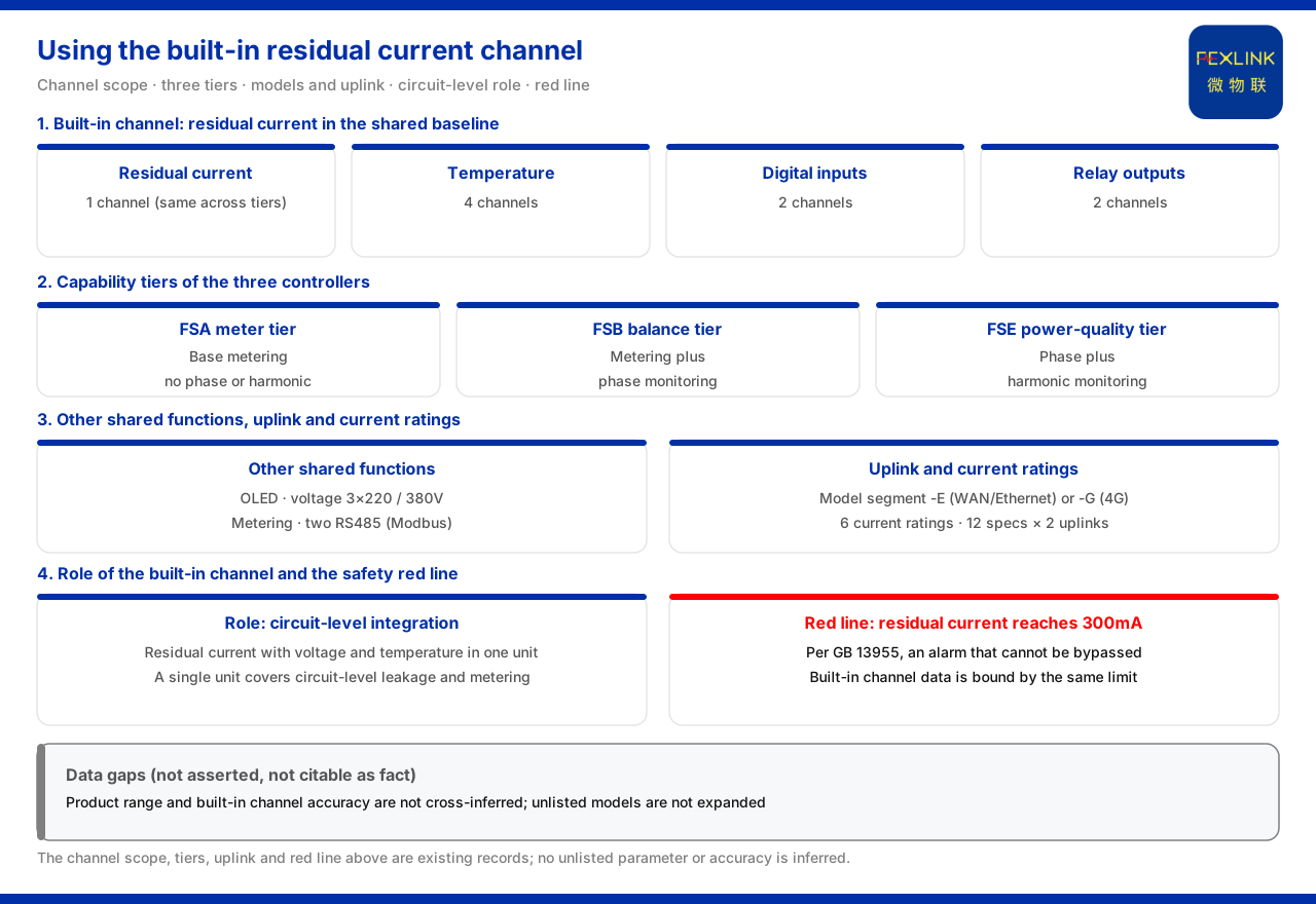
Direct answer
Under the product knowledge base, all three series of the multi-parameter electrical intelligent controller — the electricity-meter type (e.g. SFA-10011-E), the three-phase balance type and the power quality type — contain 1 residual-current channel, and also share common functions such as voltage 3×220/380V, temperature monitoring 4 channels, digital input 2 channels, relay output 2 channels, electricity-meter monitoring and two RS485 (Modbus) channels. The built-in 1 residual-current channel is therefore not an isolated leakage acquisition but a loop-level capability sitting on the same device as metering, temperature, digital input and relay output. In selection, if a single device is to perform loop-level residual-current monitoring and electricity-meter metering at the same time, it lands on these three controllers; if multiple-loop leakage, or residual current measured together with temperature, is required, one should turn to standalone products such as the multi-channel leakage-current monitoring & control device or the electrical fire monitoring & control device. The difference among the three is whether phase monitoring is added on top of electricity-meter monitoring and whether harmonic monitoring is added further.
1. The built-in channel specification is stated first
The product knowledge base lists the common functions of the three controllers one by one, and the residual-current entry is written as 1 channel. That is, whether the electricity-meter type, the three-phase balance type or the power quality type is chosen, the built-in residual-current channel is one channel only and does not increase with the type. The other common entries listed alongside it include temperature monitoring 4 channels, digital input 2 channels and relay output 2 channels. Reading these entries together makes the role of the channel clear: it faces a single loop rather than multi-loop simultaneous acquisition; where multiple loops of leakage must be covered on one device, the answer does not lie here.
2. How the three controllers divide the work
The product knowledge base arranges the three controllers in an order of increasing capability. The electricity-meter type (FSA) is basic electricity-meter monitoring without phase or harmonic functions; the three-phase balance type (FSB) adds phase monitoring on the basis of electricity-meter monitoring; the power quality type (FSE) adds harmonic monitoring on top of phase monitoring, and the material notes that the power quality type corresponds to naming such as SFE-11111-R. This progression shows that the three share the same common chassis and differ in the capability added on top, while the built-in residual-current channel belongs to the common chassis and is present on all three. In other words, the choice of type answers "do I want phase, do I want harmonics", which is a question independent of "is there a residual-current channel".
3. Common capabilities and how to read the models
The product knowledge base lists further common functions of the three: OLED display, voltage 3×220/380V, electricity-meter monitoring and two RS485 (Modbus) channels. In addition, the product material gives the general code of the electrical-safety module, which can be used to read the model positions: supply position 1 stands for DC5V and 2 for AC220V; display position 1 stands for digital tube (G) and 2 for OLED (O); communication position R stands for RS485 (Modbus). This set of codes shows that the model itself describes the configuration of supply, display and communication. The built-in residual-current channel, by contrast, is a common item at the function level and is not added or removed through a position, so it does not appear as an "option" in the model positions but is a capability shared by all three.
4. Networking and current specifications
The product knowledge base gives the model ranges and networking methods of the three: the electricity-meter type is SFA-10011 to 10061, the three-phase balance type is SFB-11011 to 11061, and the power quality type is SFE-11111 to 11161; each range can choose -E (WAN/Ethernet) or -G (4G) as the networking method. The current specifications cover six steps: 3×5A, 3×100A, 3×200A, 3×400A, 3×600A and 3×1000A. The material further states that the three together provide 12 current specifications and 2 networking methods. The correspondence between model range and current step is the place where loop capacity and networking conditions are checked together during selection: first land on the current step according to loop capacity, then choose between -E and -G according to the site network conditions.
5. What role the built-in channel can take
Bringing the common items above together, the positioning of the built-in 1 residual-current channel can be summarised as "loop-level integration". On the same controller, residual current sits together with voltage, temperature, digital input, relay output and electricity-meter monitoring, which means that a single device can complete the loop-level combination of leakage and metering. This brings two direct consequences: first, the number of monitoring points in a solution can be reduced, since residual-current monitoring need not occupy a separate standalone device; second, when judging one loop, the residual-current reading can be observed together with the temperature and digital signals of the same device. This article explains only the capability combination and infers no specific accuracy or effect.
6. Division of labour with standalone leakage products
The product knowledge base also has standalone products for residual current and leakage. The electrical fire monitoring & control device (e.g. ESF-22110-R) contains 1 residual current and 4 temperature channels, with a residual-current measurement range of 10 to 3000mA (accuracy class 1), NTC temperature measurement with a range of -20 to 100℃ (±1℃), and an external lead length of 1m; the multi-channel leakage-current monitoring & control device (e.g. ESC-22310-R) provides 1 or 3 leakage channels, with leakage measurement likewise 10 to 3000mA (accuracy class 1) and relay contact capacity AC250V/3A and DC30V/3A. Comparing these entries with the built-in channel of the three controllers shows the division of labour: the three controllers combine residual current with metering and other functions, suiting loop-level combination; the standalone products are more focused on the number of leakage channels, or on measuring residual current together with temperature. Selection is not a matter of one replacing the other but of landing on the corresponding product according to the measured object and the number of loops.
7. The red line still applies
The product knowledge base records that the basic vital-sign sub-model of the Qianzhi engine places leakage as "time-series trend plus red-line pre-position", and its red-line guard stipulates that a residual current reaching 300mA triggers a non-bypassable alarm, with GB 13955 as the basis. The data produced by the built-in 1 residual-current channel is subject to this bottom line after entering judgement. That is, the built-in channel simplifies deployment but does not change the red-line criterion: a situation reaching the threshold must be responded to unconditionally.
Scope and limitations
First, this article explains only the specification and use of the residual-current channel built into the three controllers listed in the product knowledge base, and introduces no parameter, standard or case not listed.
Second, the common functions of the three (residual current 1 channel, temperature monitoring 4 channels, digital input 2 channels, relay output 2 channels, OLED display, voltage 3×220/380V, electricity-meter monitoring and two RS485 channels) are limited to the material entries; this article infers no other element not listed.
Third, the capability progression of the electricity-meter type, the three-phase balance type and the power quality type, and the naming such as SFE-11111-R, are limited to the material; this article expands no unlisted model.
Fourth, the networking methods (-E, -G), the model ranges and current-specification steps, and the statement that the three together provide 12 current specifications and 2 networking methods, are cited as given; this article gives no other interpretation of the counting.
Fifth, the general code (supply position, display position, communication position) is listed by the material for reading the model positions; this article infers no unlisted configuration from it.
Sixth, the parameters of the standalone products (electrical fire monitoring & control device, multi-channel leakage-current monitoring & control device) are limited to their respective material entries; this article infers no range or accuracy of the built-in channel from them.
Seventh, a residual current reaching 300mA triggering a non-bypassable alarm, with GB 13955 as the basis, is cited as given; this article lists no other graded threshold and provides no selection or configuration calculation for a specific project.