 FEXLINK Research Institute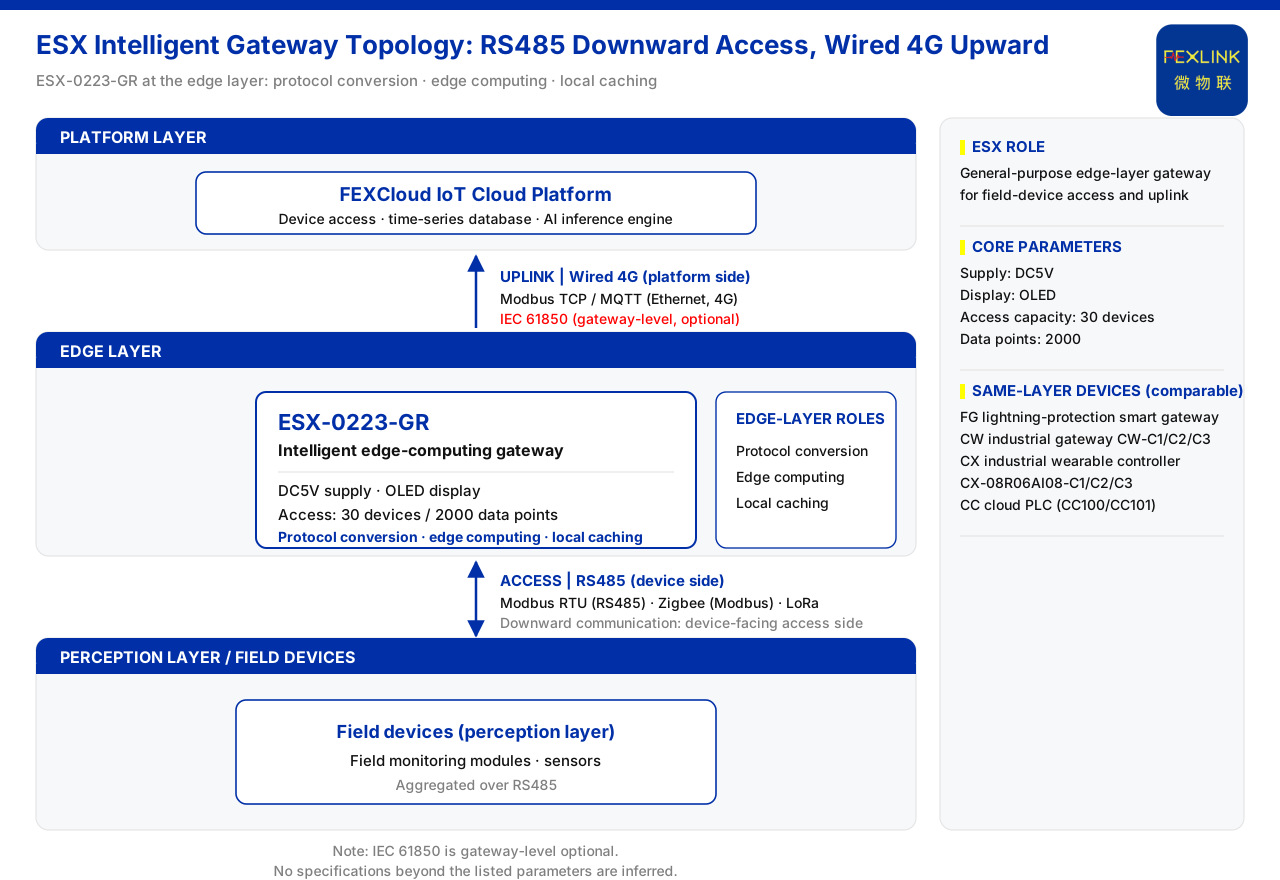
The ESX intelligent edge-computing gateway (ESX-0223-GR) is a gateway device deployed at the edge layer of a monitoring system. Downward, it acquires field-device data over RS485; upward, it sends that data to a cloud platform over wired 4G; and locally it performs protocol conversion, edge computing and data caching. On core parameters, it uses DC5V supply, carries an OLED display, and its per-unit access capacity is 30 devices and 2000 data points. To answer "what is it", the question splits into three parts: which layer of the architecture it stands at, how many devices and data points it can connect, and in what protocol and direction its data flows.
1. System Role: the Connecting Node Within the Edge Layer
The general architecture of a Weiwulian monitoring system has four layers — perception, edge, platform and application — and the device discussed here belongs to the edge layer. Under the knowledge base's definition, the edge layer is composed of gateway devices such as the FG lightning-protection smart gateway, the intelligent edge-computing gateway and industrial gateways, together with industrial wearable controllers and cloud PLCs, and jointly undertakes protocol conversion, edge computing and local caching.
Placed within the data chain, the edge layer sits exactly between the perception side and the platform side: data generated by field monitoring modules and sensors is first collected at the edge layer, then organised, converted and cached before it is sent upward; the platform layer's FEXCloud IoT cloud platform handles device access, the time-series database and the AI inference engine, and receives the data sent up by the edge layer. The layer is therefore not a simple cable adapter but a processing step that turns field data into platform-usable data. In summary, the intelligent edge-computing gateway is a general-purpose gateway within the edge layer, oriented to field-device access and upstream data transmission.
What protocol conversion, edge computing and local caching each mean
Protocol conversion means that the upward and downward communication protocols are not the same, and the gateway translates between them so that field devices can converse with the upper platform. Edge computing means that part of the processing is completed on the gateway side, close to the data source, rather than sending all raw data to the cloud first. Local caching means that when the upstream link is unstable or interrupted, data can be stored temporarily on the local side and back-filled once the link recovers, reducing the risk of data loss.
As a product-role statement, the knowledge base gives these three general responsibilities; the computation logic, cache depth and conversion rules of a particular project are governed by the actual configuration and engineering scheme, and this article infers nothing beyond the parameter table and architecture description.
2. Core Parameters at a Glance
| Model | Supply | Display | Access capacity | Downward communication | Upward communication |
|:--|:--|:--|:--|:--|:--|
| ESX-0223-GR | DC5V | OLED | 30 devices / 2000 data points | RS485 | Wired 4G |
The table reflects the parameter-table convention for this gateway and is the basis for the discussion that follows. Each of the six fields answers one selection question: supply determines the cabinet-side power take-off, display whether panel-level observation is possible, access capacity how many field devices and data points can be carried, and the two communication fields how the gateway interfaces with the field and the platform.
3. Downward and Upward: the Round Trip of One Data Path
Per the parameter table, this gateway's downward communication is RS485 and its upward communication is wired 4G. Set against the communication-protocol matrix, the path becomes clearer:
- Device downlink: the matrix lists Modbus RTU (over RS485), Zigbee (Modbus) and LoRa.
- Device uplink: the matrix lists Modbus TCP / MQTT (carried over Ethernet and 4G) and IEC 61850; IEC 61850 is gateway-level and optional.
Aligning the two: the downward RS485 meets the Modbus RTU in the downlink matrix, and the upward wired 4G meets the 4G bearer in the uplink matrix. The typical data path is therefore: field devices connect over RS485, the gateway completes conversion, and data is sent upward over wired 4G to the FEXCloud IoT cloud platform. The key point is direction — RS485 is the device-facing access side, wired 4G the platform-facing uplink side; the two are not interchangeable, nor should an uplink protocol be conflated with a downlink protocol.
4. How to Read Access Capacity: 30 Devices and 2000 Data Points
The two figures given for access capacity are 30 devices and 2000 data points. Understanding them is critical to selection: the device count caps the number of physical devices that can be mounted, and the data-point count caps the total number of data items that can be acquired and forwarded. They are not the same dimension — a single device may contribute multiple data points. To assess whether one gateway is sufficient, the field's device count and total point count must be examined together, and the line that satisfies both taken.
When the field scale approaches or exceeds these two limits, the usual approach is zoned access or more gateways; how points are divided and whether cascading is needed should be determined by actual engineering. Only the meaning of the parameters is given here; capacity or performance indicators absent from the parameter table are not extended.
5. Boundary With Same-Layer Devices
Within the edge layer, the intelligent edge-computing gateway is not the only device. The same layer also contains industrial gateways (CW-C1/C2/C3), industrial wearable controllers (programmable device wearables) (CX-08R06AI08-C1/C2/C3) and cloud PLCs (including expansion modules, such as CC100/CC101); they likewise face field-data acquisition and upstream transmission, but their product roles and parameters differ, forming a comparable group.
For selection, a clear boundary matters more than a high or low parameter. The identifiable features of this gateway are its DC5V supply, OLED display, 30-device / 2000-data-point access capacity, and the communication combination of RS485 downward and wired 4G upward. If the site needs another form of edge device, the corresponding product's parameter table and model rule should be checked instead; parameters of different products must not be applied to one another.
6. The Decision View: When It Gets Selected
Gateway selection usually answers three questions first: what interface the field devices use, where the data ultimately goes, and how the upstream link runs. For this gateway the answers are RS485, the FEXCloud IoT cloud platform, and wired 4G. When field devices connect over RS485, 4G coverage is available, and data is to enter the cloud platform directly, it is a natural candidate.
Conversely, if there is no 4G on site, or the access scale clearly exceeds 30 devices / 2000 points, the edge-device form and networking must be re-evaluated. The principle is to treat the two capacity figures and the two communication directions as screening conditions, not any single device as a universal answer.
7. Deployment and Selection Points
The following order can be used as an on-site checklist:
- Confirm the downward interface: whether field devices converge over RS485, and whether the protocol used is the Modbus RTU in the downlink matrix.
- Confirm the upward link: whether wired 4G is available on site, and whether data is to be sent to the FEXCloud IoT cloud platform.
- Check the access scale: count devices and data points, and confirm both are within the 30-device and 2000-point range.
- Check supply and display: the supply is DC5V with an OLED display, so provision is needed for cabinet power and panel observation.
- Check protocol options: if IEC 61850 is involved, note that it is a gateway-level optional capability governed by the final configuration.
This order uses only information in the parameter table and protocol matrix; for schemes involving other devices or protocols, the respective product documentation must be consulted.
Applicability and Limits
- This article is aimed at English-language readers, and its content is limited to the ESX intelligent edge-computing gateway (ESX-0223-GR) parameter row, the edge-layer and platform-layer descriptions, the protocol matrix, and existing same-layer device entries in the knowledge base.
- The parameters are only the parameter-table convention for this model: DC5V supply, OLED display, access capacity of 30 devices / 2000 data points, downward RS485, upward wired 4G; they do not include performance, certification, environmental-adaptation or field-case conclusions beyond the parameter table.
- Names such as Modbus, MQTT and IEC 61850 in the protocol matrix are cited as listed, with IEC 61850 gateway-level and optional; which one a project adopts is governed by the engineering configuration.
- Comparisons involving other edge-layer devices explain only their same-layer relationship and do not replace the respective products' parameters and selection materials; parameters of different products must not be applied to one another.
- This article is not a commitment to any unlisted indicator; where field conditions differ from its premises, the latest product documentation and actual engineering scheme prevail.