 FEXLINK Research Institute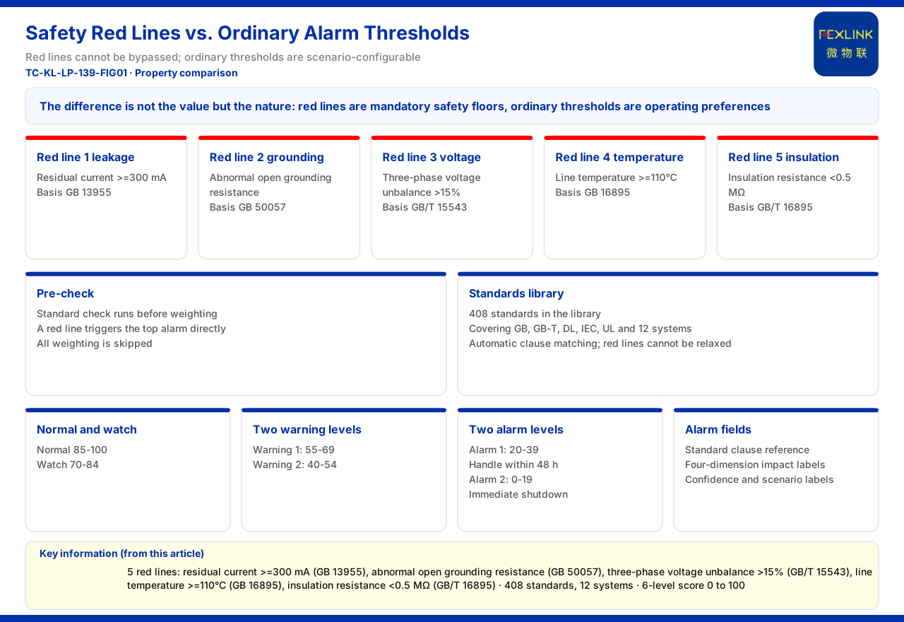
Direct answer
Among lightning-protection alarms, one class of rule cannot be lumped together with ordinary thresholds: the safety red-line. The product material lists five safety red-lines and states explicitly that they cannot be bypassed and that no one can raise their thresholds. Ordinary alarm thresholds, by contrast, can be configured per scenario. The difference is not in how high or low the numbers sit but in their nature: a safety red-line corresponds to a safety floor mandated by standards, whereas an ordinary threshold corresponds to an on-site operating preference. Only by understanding this can one explain why some alarms can never be loosened, and why the two rule classes must be managed separately in product design and operations.
1. A safety red-line is not merely a stricter threshold
Many sites read a safety red-line as an alarm line set more strictly. That sees only the numeric surface. The product material describes safety red-lines as non-bypassable and stresses that no one can raise their thresholds. This means a safety red-line is not a configuration item that permission, scenario or parameter can override; it is a floor that the decision flow must execute unconditionally. An ordinary threshold is the opposite: it serves operations management, and the reasonable point of attention for the same device legitimately changes with load, process and season. Placing both in one configuration screen easily leads users to assume that a safety red-line can be adjusted like an ordinary threshold. That is the first layer of understanding to clarify.
2. Each of the five safety red-lines anchors one class of physical quantity
The product material lists the trigger condition and basis of each safety red-line: residual current reaching 300 mA or above, per GB 13955; abnormal open of grounding resistance, per GB 50057; three-phase voltage unbalance exceeding 15%, per GB/T 15543; line temperature reaching 110°C or above, per GB 16895; and insulation resistance below 0.5MΩ, per GB/T 16895. The five fall respectively on leakage, grounding, voltage, temperature and insulation, all quantities that point directly to consequences for personal and equipment safety. Because they carry mandatory safety requirements, they cannot be relaxed at will by users the way process thresholds can. In other words, a safety red-line constrains whether a floor has been crossed, not whether operation is economical.
3. Why ordinary alarm thresholds can be configured per scenario
Alongside the safety red-lines, the product material describes a six-level alarm system. It grades by a composite score of 0 to 100: normal 85 to 100, watch 70 to 84, level-1 pre-warning 55 to 69, level-2 pre-warning 40 to 54, level-1 alarm 20 to 39 requiring disposition within 48 hours, and level-2 alarm 0 to 19 requiring immediate shutdown. This grading is the common framework through which device-side collected elements enter alarm decisions, and the ordinary tiers face risk and operations rhythm, so they inherently carry scenario attributes. Different sites tolerate watch and pre-warning differently, so these thresholds need to be configurable. Note, however, that the product material gives neither the adjustable range of ordinary thresholds nor the adjustment permissions, nor the configuration rules for their coexistence with safety red-lines; these must not be filled in by imagination.
4. Pre-checks make safety red-lines effective before weighting
The product material also explains why a safety red-line cannot be calculated away. In the pre-position responsibilities of the seven-stage pipeline, the third stage is standards verification, the safety red-line pre-check. It runs before the relevant sub-models perform weighted calculation; once a safety red-line is triggered, the system directly outputs the highest-level alarm corresponding to the lowest score tier and skips all weighted computation. The point of this design is that the conclusion of a safety red-line is not decided by the downstream scoring model, so there is no possibility of diluting it through parameter tuning, weighting or scenario tags. For users this means a safety red-line alarm and an ordinary graded alarm are not equivalent in credibility; the former carries a higher priority and a stricter disposition requirement.
5. A standards library and clauses underpin non-relaxability
The safety red-lines are hard also because a standards library backs them. The product material records that the standards service provided by the Taiyi intelligent-control hub targets safety red-line compliance; the library contains 408 standards covering 12 systems including GB, GB-T, DL, IEC and UL, can match clauses automatically, and the red-lines cannot be relaxed. The standards-verification stage of the seven-stage pipeline undertakes the safety red-line pre-check. Binding standard clauses to alarms means every safety red-line alarm can be traced to a specific basis, for example a grounding-type safety red-line to GB 50057. This also explains why a safety red-line is an explainable hard constraint: it is not a vendor-defined empirical line but the operational landing point of a mandatory standard requirement.
6. Management implications of the two rule classes
Distinguishing safety red-lines from ordinary thresholds is directly useful to both client and vendor. For the client's safety lead, safety red-lines are acceptance and compliance check items and should not be treated as negotiable technical indicators, while ordinary thresholds should be confirmed against operating conditions to avoid excessive alarms. For engineering companies and solution engineers, the collection capability for safety red-line elements should be a precondition of selection, and ordinary-threshold configuration should be left to the commissioning stage. For product designers, the interface must clearly distinguish the permissions of the two rule classes to prevent a non-bypassable item from being mistakenly placed in an editable area. Presenting the standard basis together with the alarm can also reduce repeated explanations of why a given line cannot be adjusted.
7. Turning the understanding into executable checks
From a management view, distinguishing the two rule classes must ultimately land in actions. The first step is identification: in the scheme or O&M document, list mandatory standard items and operating-preference items separately, and classify everything traceable to bases such as GB 13955, GB 50057, GB/T 15543, GB 16895 and GB/T 16895 as a safety red-line. The second step is confirming the boundary: a safety red-line only judges whether a line is crossed and does not participate in economic trade-offs, so it should not appear in the adjustable-parameter list. The third step is checking collection capability: for a safety red-line to take effect, the front end must be able to collect the corresponding physical quantity, for example a grounding-type safety red-line requires grounding-resistance monitoring capability. The fourth step is leaving a trace: let every safety red-line alarm carry its standard basis for later review. These steps are not complex, but they turn the statement that safety red-lines cannot be adjusted from a slogan into a checkable requirement. To add, this set of checks does not change the product's own capability boundary; it merely organizes existing facts into an order convenient for review, while actual collection and alarming are still completed by field devices and the platform according to their respective responsibilities.
Scope and limitations
First, this article explains only the nature difference between safety red-lines and ordinary thresholds; the factual boundary is limited to the product material, and no adjustable range, permission or coexistence-configuration rule not given there is inferred.
Second, the five trigger conditions and their basis standards are as recorded in the product material; this article does not extend other standard clauses from them, nor does it judge whether a specific project meets a standard.
Third, the product material does not provide the specific configuration method for ordinary thresholds or safety red-lines; the management suggestions here are a general induction from the listed facts and do not constitute a configuration scheme.
Fourth, the safety red-line check and alarm configuration of a specific project must be determined in conjunction with on-site standard applicability and O&M requirements; this article provides no selection calculation or compliance conclusion.