 FEXLINK Research Institute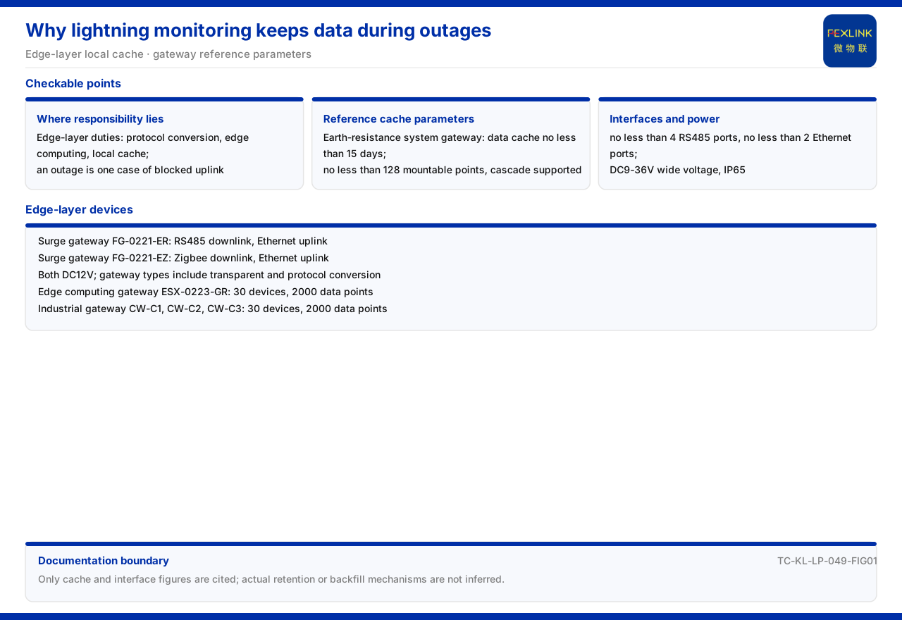
Direct Answer
Lightning-protection monitoring does not lose data during a network outage because of local caching at the edge layer. The product documentation states the responsibilities of the edge layer explicitly as protocol conversion, edge computing, and local caching; local caching means that when upward transmission is blocked, data can first remain in the field device. Among the reference parameters for the grounding resistance monitoring system's intelligent gateway, the data cache is no less than 15 days, and reference values are also given for mounted points, interface count, power supply, and protection rating. In other words, loss-free data during an outage is not a promise but something supported jointly by the local storage capability and the interface capability of the edge device. This article cites only these caching and interface definitions and does not infer the actual retention time at a site after an outage.
1. Loss-Free Data During an Outage Relies on Edge-Layer Local Caching
Data travels from the field to the platform through the perception layer and the edge layer. The documentation summarizes the monitoring system as four layers — perception layer, edge layer, platform layer, and application layer — and the edge layer's responsibilities include protocol conversion, edge computing, and local caching. Of these three, protocol conversion solves "how different devices speak the same language," edge computing solves "doing part of the processing locally first," and local caching solves "where data is placed when the uplink is blocked."
An outage is one case of a blocked uplink. If the field device has no local caching capability, data may be lost while waiting for the uplink; with local caching, data can first be written to local storage and uploaded after the link recovers. The discussion of "loss-free data during an outage" therefore lands not on the platform layer but on the edge layer's local caching capability. Locating the responsibility correctly is what explains why the caching parameter below appears in the gateway reference parameters rather than on the platform side.
2. Caching and Interfaces in the System Reference Parameters
The reference parameters of the grounding resistance monitoring system's intelligent gateway are the key to understanding outage retention. These parameters include: a data cache of no less than 15 days, no fewer than 128 mounted points with cascade capability, no fewer than 4 RS485 ports, no fewer than 2 Ethernet ports, a DC9-36V wide-voltage supply, and an IP65 protection rating.
Of these, the one most directly related to outage retention is the data cache of no less than 15 days: it gives the lower-bound definition of local retention time. The rest describe the gateway's access and deployment conditions — mounted points and cascade capability determine how many monitoring points can be connected, the RS485 and Ethernet port counts determine the available wired channels, and wide-voltage supply and IP65 determine field adaptability. The boundary is that these are reference parameters of a system-level intelligent gateway; this article cites them on that basis, does not equate them with per-item indicators of one specific model, and does not infer how much data can be fully retained for 15 days after an actual outage.
3. What Other Devices the Edge Layer Contains
Local caching is not carried by one gateway alone; the edge layer itself contains several devices. The documentation records that the edge layer contains the lightning-protection smart gateway, the intelligent edge-computing gateway, and the industrial gateway, as well as the industrial wearable and the cloud PLC. They each carry different parts of the responsibilities of protocol conversion, edge computing, and local caching, and together aggregate field data and pass it upward.
From the layering perspective, the edge layer sits between the perception layer and the platform layer, and its devices must dock downward with monitoring modules and upward with the platform. Edge devices therefore usually have both downlink and uplink interfaces and complete conversion and caching between them. The documentation does not expand the specific behavioral differences of each edge device in an outage, so this article explains only the overall edge-layer responsibilities and device composition and does not infer a single device's handling details when a link breaks.
4. The Model and Role of the Lightning-Protection Gateway
In lightning-protection monitoring scenarios, the lightning-protection smart gateway is a common edge-layer device. The documentation records that its model rule encodes gateway type, installation method, power supply, downlink, and uplink by digit, and the gateway-type position contains two values: transparent transmission and protocol conversion. "Protocol conversion" is therefore a capability identifiable through the model code, not something every gateway has by default.
The available models recorded are the lightning-protection smart gateway (FG-0221-ER) and (FG-0221-EZ). Both use DC12V supply and are of the protocol-conversion type; the former has an RS485 downlink and Ethernet uplink, and the latter a Zigbee downlink and Ethernet uplink. These models show that, as protocol-conversion gateways, the difference lies in the downlink: one uses wired RS485 and the other wireless Zigbee, while the uplink is Ethernet in both. Protocol conversion is exactly the responsibility of turning data acquired on the downlink into a format that can be transmitted upward, and local caching ensures that data is not immediately lost when the upward path is blocked.
5. Edge-Computing Gateway and Industrial Gateway
Besides the lightning-protection smart gateway, the edge layer also has the edge-computing gateway and the industrial gateway. The documentation records that the intelligent edge-computing gateway (ESX-0223-GR) uses DC5V supply, has an OLED display, an access capability of 30 devices and 2000 data points, an RS485 downlink, and a wired 4G uplink. Its upward channel is wired 4G, which forms a different choice from the Ethernet uplink of the lightning-protection smart gateway.
On the industrial gateway, the documentation records three models: the industrial gateway (CW-C1), (CW-C2), and (CW-C3). CW-C1 uses DC24V, an RS485 downlink, and an Ethernet uplink; CW-C2 adds 4G on that basis; and CW-C3 has an RS485 and Zigbee downlink with an Ethernet uplink. All three share an access capability of 30 devices and 2000 data points. Listed together, they show that the edge layer has many combinations of power supply, downlink, and uplink, and selection must match the on-site channel conditions.
6. Protocol and Uplink Connection
The caching and conversion of edge devices finally rest on protocol connection. The communication protocol matrix in the documentation lists the device downlink and uplink protocols: the device downlink contains Modbus RTU (RS485), Zigbee, and LoRa, while the device uplink contains Modbus TCP and MQTT (Ethernet, 4G), with IEC 61850 optional at the gateway level. This matrix shows that the edge layer must support several field buses and wireless methods downward and protocols based on Ethernet and 4G upward.
When the uplink breaks, the local cache of the edge device keeps data from being lost immediately; when the link recovers, the cached data continues upward through the uplink protocol. The documentation gives the caching and interface parameters and the protocol matrix, but not the complete outage-reconnection flow or the backfill rule, so this article states only the existence of caching and protocols and their connection, and does not infer the specific backfill mechanism.
Scope and Limitations
First, this article restates only what the product documentation lists, and its factual boundary is limited to the edge-layer responsibilities and device composition, the intelligent gateway reference parameters, the model parameters of the lightning-protection gateway, edge-computing gateway, and industrial gateway, and the communication protocol matrix.
Second, the data cache of no less than 15 days, no fewer than 128 mounted points with cascade capability, no fewer than 4 RS485 ports, no fewer than 2 Ethernet ports, DC9-36V wide voltage, and IP65 of the grounding resistance monitoring system's intelligent gateway are cited as listed in the system-level reference parameters; this article does not equate them with per-item indicators of one specific model.
Third, the DC12V, protocol-conversion type, downlink methods, and Ethernet uplink of the lightning-protection smart gateway (FG-0221-ER, FG-0221-EZ) are cited as listed in the model table; this article does not supplement unlisted models.
Fourth, the DC5V, OLED, 30 devices, 2000 data points, and uplink and downlink methods of the intelligent edge-computing gateway (ESX-0223-GR), and the power supply, downlink, uplink, and access capability of the industrial gateway (CW-C1, CW-C2, CW-C3), are cited as listed; this article does not infer on-site deployment differences.
Fifth, the device downlink and uplink protocols and carriers in the communication protocol matrix are cited as listed; this article does not infer the specific mechanism of outage reconnection and data backfill.
Sixth, a concrete outage-retention scheme must be fixed against site link conditions, caching-duration requirements, and operation requirements; this article provides no configuration calculation, and the latest product documentation and formal documents prevail in practice.