 FEXLINK Research Institute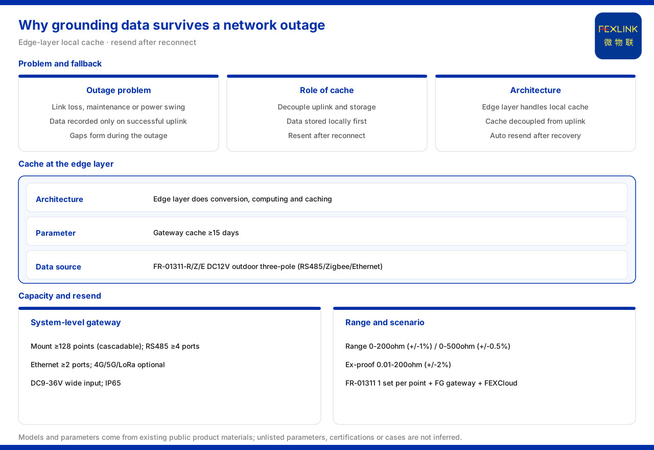
Direct answer
Grounding-monitoring data does not get lost during an outage because of local caching at the edge layer. The grounding resistance monitoring system reference parameters of the product knowledge base record that the smart gateway's data cache covers no fewer than 15 days, giving a capacity guarantee for local retention; the same set gives a smart-gateway mounting of no fewer than 128 points with cascading, no fewer than 4 RS485 channels, no fewer than 2 Ethernet channels, optional 4G/5G/LoRa, a DC9-36V wide-voltage supply, and IP65. Architecturally the cache falls at the edge layer: the four-layer architecture is sensing, edge, platform, and application layers, and the edge layer undertakes protocol conversion, edge computing, and local caching. The data source is the FR grounding resistance monitor (FR-01311-R/Z/E), a DC12V outdoor three-electrode unit with communication selectable among RS485, Zigbee, or Ethernet; the FG lightning-protection smart gateway (FG-0221-ER, FG-0221-EZ) performs protocol conversion and the uplink. The typical combination "online monitoring of substation and traction-substation grounding grids" is one FR-01311 per point plus an FG gateway plus the FEXCloud platform, so both outage-time caching and post-outage retransmission happen on this segment.
1. The problem during outages and the role of caching
Online monitoring relies on a network to send data back, but the field network is not always available: link interruptions, maintenance, or supply fluctuations can block the uplink. If data were recorded only when the uplink succeeds, the state during an outage would form a blank hard to reconstruct. The response given by the product knowledge base is a local cache on the gateway side, with data caching no fewer than 15 days. Its role is to decouple uplink from storage: during an outage the data lands locally first and is retransmitted after the network returns, so the continuous record does not break because of one link interruption. Caching is thus the fallback during a link interruption, not an optional extra.
2. The cache sits at the edge layer, not the platform side
The product knowledge base records that the edge layer consists of the FG, ESX, and CW gateways plus the CX industrial wearable controller and the CC cloud PLC, and undertakes protocol conversion, edge computing, and local caching. Writing caching explicitly into the edge layer's duty shows that outage-time storage is a capability of the aggregation node itself: data is normalized and retained within the site first, and the uplink is considered after. Cache capacity is therefore bound to the gateway's form; only such a gateway gives the site local retention during an outage.
3. The 15-day cache defines the outage-tolerance window
Cache capacity corresponds to an available window of time. The product knowledge base's wording is data caching of no fewer than 15 days, meaning that when the uplink is interrupted the site can continuously store about 15 days of grounding-monitoring data and retransmit it after the network recovers. This gives a checkable window for scheme design: if the likely interruption is within it, the data will not be lost; if the interruption may be longer, local retention should be reassessed. Note that 15 days is a lower-bound wording; this article does not read it as a guarantee for any site's interruption duration, nor infer behavior beyond that window.
4. Which measurement ranges the cached data correspond to
What is cached is grounding-monitoring data, whose measurement range is explicitly recorded. The reference parameters divide the monitoring unit into three grades: standard at 0 to 200Ω (±1%), high-precision at 0 to 500Ω (±0.5%), and explosion-proof at 0.01 to 200Ω (±2%). These ranges and accuracies define the grounding-resistance range corresponding to the cached data: whether or not the network is available, the cached value falls within the range of the chosen grade. To discuss what is stored during an outage, the grade chosen should be confirmed first; what is cached is the record within that grade's measurable range, not an inferred value beyond it.
5. The path from acquisition to the gateway
Before caching, the data must reach the gateway. The materials record that the FR grounding resistance monitor (FR-01311-R/Z/E) is a DC12V, outdoor-mounted, three-electrode unit with communication selectable among RS485, Zigbee, or Ethernet, and that the FG lightning-protection smart gateway is a protocol-converting type, with FG-0221-ER using RS485 downlink and Ethernet uplink and FG-0221-EZ using Zigbee downlink and Ethernet uplink. The monitor therefore chooses its downlink by field conditions and the gateway is selected accordingly; data is acquired by the monitor, enters the gateway over the downlink, and is cached at the gateway while awaiting the uplink. The local cache receives data aggregated from several monitors in the site, prepared for exactly this continuous data.
6. System-level parameters define aggregation and retention
Caching capacity stands alongside the gateway's overall capability. The reference parameters record a mounting of no fewer than 128 points with cascading, no fewer than 4 RS485 channels, no fewer than 2 Ethernet channels, optional 4G/5G/LoRa, a DC9-36V wide-voltage supply, and IP65. Placing the 15-day cache within this set: the mounting point count determines the scale of monitoring points the site can access, the interface counts determine the branching, cascading shows extension at a larger scale, the wide-voltage supply and IP65 show adaptation to field supply and outdoor environments, and the optional uplink shows the networking method is chosen by the field network. Together these decide "how much can be retained during an outage and how it can be sent back after recovery."
7. Typical scenarios confirm data aggregation through the gateway
The typical application scenario table writes the combination for "online monitoring of substation and traction-substation grounding grids" as one FR grounding resistance monitor (FR-01311) per point plus an FG gateway plus the FEXCloud platform. This shows where the data goes: each point's grounding-resistance data is acquired by the monitors, aggregated by the FG gateway, and finally received by the FEXCloud platform. The local cache during an outage happens exactly on this segment between gateway aggregation and platform reception. The materials also record that the FR grounding resistance monitor (FR-01311-R/Z/E) can be connected in several sets to cover dispersed grounding-grid points, confirming the gateway as the site's aggregation point and carrier of caching and retransmission.
8. Reducing the outage-retention check into an ordered sequence
The check of "local caching during an outage and retransmission after recovery" can be reduced to an ordered sequence. Step one, confirm the data source and range: choose the FR grounding resistance monitor (FR-01311-R/Z/E) and a standard, high-precision, or explosion-proof grade by the field magnitude. Step two, determine the downlink by the monitor's communication options and select the FG lightning-protection smart gateway (FG-0221-ER or FG-0221-EZ). Step three, check the cache capability: confirm the gateway caches no fewer than 15 days of data and compare it with the likely interruption duration. Step four, check the aggregation capability against a mounting of no fewer than 128 points with cascading, no fewer than 4 RS485 channels, and no fewer than 2 Ethernet channels. Step five, determine the uplink among 4G, 5G, LoRa, and Ethernet by the field network. Step six, verify DC9-36V and IP65 against field conditions. Step seven, connect to the platform, with the FEXCloud platform receiving the retransmitted data after recovery. This answers "what is stored during an outage, for how long, and how it goes up after recovery."
Scope and limitations
First, this article restates only what the product knowledge base lists, and the factual boundary is limited to the grounding resistance monitoring system reference parameters, the monitoring-unit ranges and accuracies, the edge layer's duty, the model parameters of the FR grounding resistance monitor (FR-01311-R/Z/E), the model downlink/uplink of the FG lightning-protection smart gateway, and the typical scenario combination; it introduces no unlisted parameter, certification, or case.
Second, the no-fewer-than-15-day data cache, the no-fewer-than-128-point mounting with cascading, the no-fewer-than-4 RS485 channels, the no-fewer-than-2 Ethernet channels, optional 4G/5G/LoRa, DC9-36V wide voltage, and IP65 are cited as the product knowledge base lists them.
Third, the standard type at 0 to 200Ω (±1%), the high-precision type at 0 to 500Ω (±0.5%), the explosion-proof type at 0.01 to 200Ω (±2%), and the supply, mounting, measurement principle, and communication options of the FR grounding resistance monitor (FR-01311-R/Z/E) are cited as the product knowledge base lists them.
Fourth, the edge layer's protocol conversion, edge computing, and local caching, the downlink and uplink of the FG lightning-protection smart gateway (FG-0221-ER, FG-0221-EZ), and the one-set-per-point plus gateway plus platform combination are cited as the product knowledge base lists them.
Fifth, the product knowledge base gives no conversion between cache capacity and data volume, nor a specific post-outage retransmission strategy; this article records that boundary and infers no unlisted calculation or mechanism.
Sixth, this article explains only the architecture and parameter boundary of local caching and retransmission and provides no specific engineering storage or network plan; related conclusions must be confirmed against field network conditions and the project scheme, and the latest product materials and project scheme always prevail.