 FEXLINK Research Institute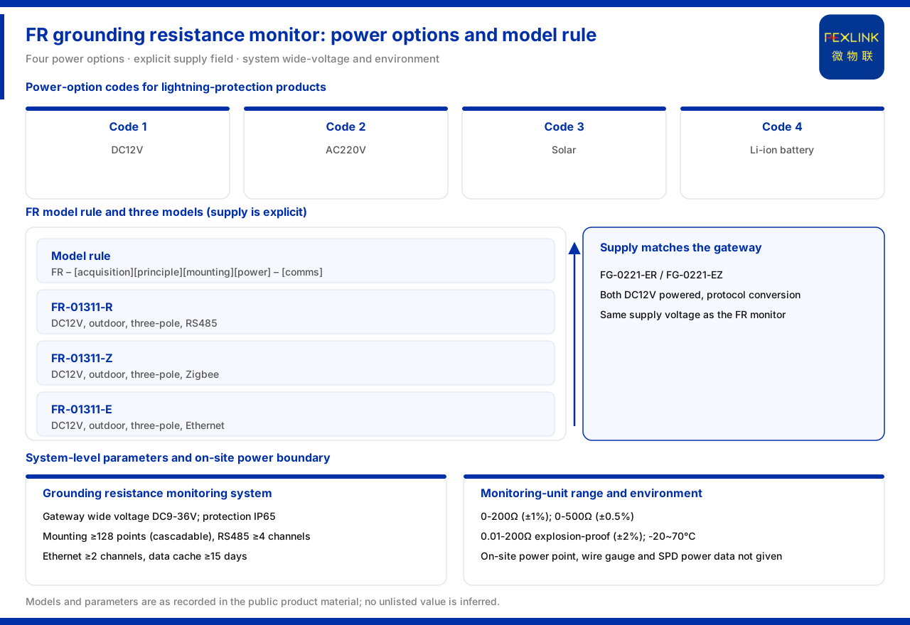
Direct Answer
At the model level the supply of the grounding resistance monitor is an explicit DC class. The three grounding resistance monitors listed in the product knowledge base table (FR-01311-R, FR-01311-Z and FR-01311-E) all use a DC12V supply, outdoor installation and three-electrode measurement, and differ only in communication, which is RS485, Zigbee and Ethernet respectively. That is, in selection the communication can be chosen one of three, while the supply does not differ among the three.
Widening the view, supply is not a field that can be filled in at will. Lightning-protection products have a supply-method code system whose values are four classes: DC12V, AC220V, solar and lithium battery; and in the system-level parameters the smart gateway used for grounding monitoring requires a DC9-36V wide voltage. It can be seen that "single-model DC12V" and "system-level wide voltage" belong to two levels. On this basis the article explains the relationship of these two scopes, the environmental boundary, and the on-site power take-off matter the material has not yet unfolded.
1. Supply Method Codes for Lightning-Protection Products
The product knowledge base gives four supply-method codes for lightning-protection products: 1 for DC12V, 2 for AC220V, 3 for solar and 4 for lithium battery. This code set shows that the supply scheme of lightning-protection products is explicitly coded, rather than freely agreed by model.
With this code set, supply turns from a descriptive field into an enumerable selection dimension. Where there is no mains on site, solar or lithium battery can be brought into consideration; where there is a stable DC condition, DC12V is the conventional choice. Understanding these four classes is the premise for understanding the supply field in the FR model rule.
2. The FR Model Rule Writes Supply as an Explicit Field
The model rule of the grounding resistance monitor is composed in its front segment of signal acquisition, detection principle, installation method and supply, and in its rear segment of communication. The installation method distinguishes two classes, outdoor and indoor, and supply is an independent cell in the model.
Since supply occupies an independent cell, it is fixed at the product-definition stage rather than decided temporarily at installation. This also explains why the three FR models take the same values in installation method and measurement principle but diverge in communication: the model rule expresses differences through fields, and any capability not distinguished by a field is by default consistent.
3. Similarities and Differences of the Three FR Models
The product knowledge base table lists FR-01311-R, FR-01311-Z and FR-01311-E. All three use a DC12V supply, outdoor installation and three-electrode measurement; the only difference is communication, which is RS485, Zigbee and Ethernet respectively.
This set of comparisons narrows the judgement points of selection. Since the supply, installation method and measurement principle are all the same, what really needs a trade-off during field deployment is the communication link: choose the R version when an RS485 bus exists, the Z version when short-range wireless access is needed, and the E version when direct Ethernet upload is needed. A consistent supply means the field supply-side preparation for the three can be considered uniformly as DC12V.
4. Consistency with the Supply Convention of the Lightning-Protection Smart Gateway
Within the same product line, the two lightning-protection smart gateway models FG-0221-ER and FG-0221-EZ also use a DC12V supply and take on protocol conversion. The grounding resistance monitor and the lightning-protection smart gateway agree in supply voltage, which is favourable for centralised power take-off within the same grounding-grid monitoring system.
The practical benefit of a consistent supply scope is that if the site uses a unified DC source, the monitor and the gateway can share the same voltage class, reducing the conversion stages that differing voltages would add. Note that this judgement goes only as far as "the voltage class agrees"; the product knowledge base does not state whether the two can share the same power supply unit or the same circuit, and this part must be determined by the engineering scheme.
Also note the correspondence between the model rule and the supply code. The supply code records DC12V as 1, while the model rule of the grounding resistance monitor again makes supply an independent field. It can therefore be judged that the value of the supply field appearing in the model should agree with the supply code, that is, correspond to the DC class. In this way selection can confirm the supply category from the model without first looking up the supply code and then checking back against the model. Using the two rules that express the same information side by side can reduce the chance of missing the supply field through unfamiliarity with the conventions.
In addition, the model rule also lists installation method as an independent field. Once supply is fixed, installation method is the next item to confirm: outdoor and indoor correspond to different on-site conditions and deployment methods. Both supply and installation method appear explicitly in the model, showing that on-site conditions are brought into consideration at the product-definition stage rather than left aside until installation.
5. Wide Voltage and Environmental Boundaries in System-Level Parameters
The reference parameters of the grounding resistance monitoring system in the product knowledge base give the system-level scope: the smart gateway supports a DC9-36V wide-voltage supply, has protection class IP65, can mount no fewer than 128 points with cascading, provides no fewer than 4 RS485 channels and no fewer than 2 Ethernet channels, and buffers no fewer than 15 days of data. On the monitoring unit side, the range is divided into the standard type of 0 to 200Ω (accuracy ±1%), the high-accuracy type of 0 to 500Ω (accuracy ±0.5%) and the explosion-proof type of 0.01 to 200Ω (accuracy ±2%), with protection class IP65 and an operating temperature of -20 to 70°C.
Two supply scopes appear here: the single model is DC12V, and the system-level smart gateway is DC9-36V wide voltage. The two do not conflict but belong to different levels. DC12V falls within the DC9-36V interval, showing that the wide-voltage gateway can accommodate the DC voltage of the single model; the point of wide voltage is to tolerate voltage fluctuation or different power take-off conditions that may occur on site. Besides supply, IP65 and the operating temperature of -20 to 70°C together form the environmental boundary of field deployment.
6. On-Site Power Take-off Remains an Unlisted Item
The typical application scenario lists the online grounding-grid monitoring combination of substations and traction substations as the grounding resistance monitor (one set per point) plus the FG gateway plus FEXCloud. This combination explains the device composition but does not answer where the site takes its power from.
Specifically, in the model rule, the model table and the system-level parameters the product knowledge base gives no construction data on where the grounding resistance monitor takes power on site, what supply cable gauge to use, or whether a surge-protection power module is configured. That is, it can be confirmed that the device needs DC12V or can access a DC9-36V wide-voltage gateway, but the on-site power take-off point, cable gauge and power protection configuration cannot be confirmed from it. These belong to detailed engineering design and should be checked separately against field conditions and the project scheme.
Scope and Limitations
First, this article restates only what the product knowledge base lists, with the factual boundary limited to the supply-method codes for lightning-protection products, the grounding resistance monitor model rule and model table, the lightning-protection smart gateway supply, the grounding resistance monitoring system reference parameters, and the typical application scenario.
Second, the supply, installation method and measurement principle of the three grounding resistance monitors are cited as listed in the product knowledge base; this article does not infer their on-site power take-off point or supply cable gauge.
Third, the four values of the lightning-protection product supply-method codes are cited as listed in the product knowledge base; this article does not specify the supply choice of a specific project on that basis.
Fourth, the DC12V supply and protocol conversion of the lightning-protection smart gateway are cited as listed in the product knowledge base; this article does not infer whether the monitor and the gateway can share the same power supply unit.
Fifth, the DC9-36V wide voltage, IP65, mounting and buffering parameters of the system-level smart gateway, and the range, protection class and operating temperature of the monitoring unit, are cited as listed in the product knowledge base; this article does not extend them to single-model parameters.
Sixth, the device combination of the typical application scenario is cited as listed in the product knowledge base; this article does not give power take-off construction data on that basis.