 FEXLINK Research Institute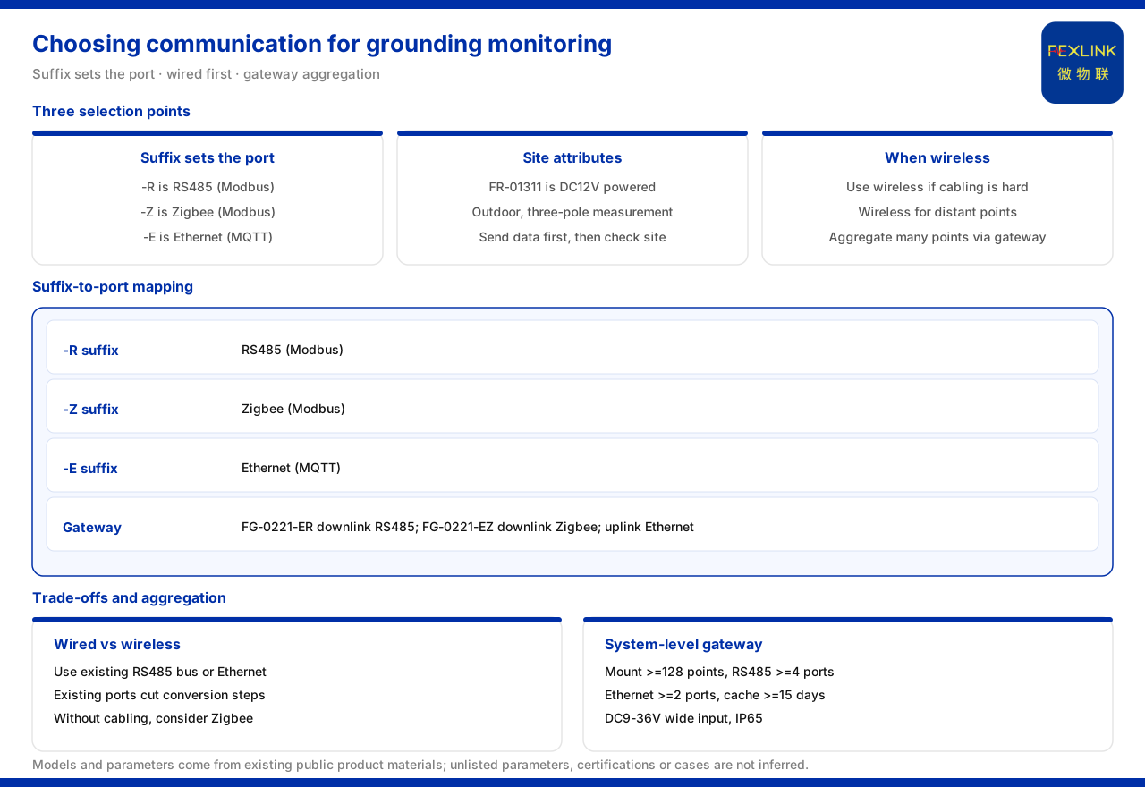
How to Choose the Communication Method for Grounding Monitoring
Direct answer: the communication method for grounding monitoring is chosen according to the on-site cabling and the transmission distance. The FR grounding resistance monitor (FR-01311) in the material distinguishes its communication method by suffix: -R for RS485, -Z for Zigbee and -E for Ethernet. In principle wired is preferred, and wireless is considered only when cabling is difficult, or when the points are scattered and far apart; when the number of monitoring points is large, they must first be aggregated through the FG lightning-protection smart gateway and then uploaded to the platform.
What the Three Communication Suffixes of FR Mean
The three suffixes of the grounding resistance monitor FR-01311 map directly to three communication methods: FR-01311-R uses RS485, FR-01311-Z uses Zigbee and FR-01311-E uses Ethernet. The material also gives the field attributes of these models: DC12V supply, outdoor installation and the three-electrode measurement method. Looking at the suffix together with the field attributes, one can first fix "how this point sends its data out" and then check whether it satisfies the outdoor supply and installation conditions.
These suffixes agree with the general convention in the material: -R means RS485 (Modbus), -Z means Zigbee (Modbus) and -E means Ethernet (MQTT). Choosing a suffix therefore not only fixes the physical interface but also implies the uplink protocol direction. For a project that already has an RS485 bus or Ethernet, choosing the suffix by the existing interface reduces conversion stages; for a site without wired conditions, the Zigbee version can be considered.
Weighing Wired Against Wireless
The trade-off between wired and wireless depends mainly on cabling feasibility and distance. RS485 suits laying along an existing cable route, with several monitoring points on the same bus, giving a stable connection and easy unified management. Ethernet suits a site that already has network coverage and needs direct network access. Zigbee is wireless and suits difficult cabling, scattered points or reduced trenching and conduit work. The material does not give the transmission distance or anti-interference figures of each method, so these can only serve as general judgement bases and must still be confirmed against field conditions.
A practical order of judgement is: first see whether a usable wired channel already exists; if so, prefer wired; if not, then evaluate whether a wireless scheme is feasible. This respects the site reality and avoids going wireless for its own sake.
The Role of the Gateway in Networking
When there is more than one monitoring point, data usually has to be aggregated before upload. The FG lightning-protection smart gateway (FG-0221) in the material is a protocol-conversion device supplied at DC12V. The FG-0221-ER has RS485 on the downlink and Ethernet on the uplink; the FG-0221-EZ has Zigbee on the downlink and Ethernet on the uplink. Both gateways unify the uplink to Ethernet, and differ only in whether the downlink is wired or wireless.
This "field on the downlink, network on the uplink" structure lets grounding monitoring points access the gateway nearby over RS485 or Zigbee and then upload over Ethernet. For a project with scattered points, gateways can be deployed by area to shorten each cabling run; for a project with concentrated points, several monitoring units can hang on the same RS485 bus and be aggregated by one gateway.
Downlink and Uplink Choices in the Communication Protocol Matrix
The communication protocol matrix in the material further explains the protocols available at each layer. The device downlink includes Modbus RTU (RS485), Zigbee (Modbus) and LoRa; the device uplink includes Modbus TCP or MQTT (Ethernet, 4G), plus gateway-level IEC 61850 (optional). This means the field side can choose among three downlink methods, the network side can choose among Ethernet, 4G and other channels, and higher-level protocols can be opened as needed at the gateway level.
In scheme terms, if the field is mainly RS485, a gateway with RS485 downlink and Ethernet uplink can be chosen; if the field is mainly Zigbee, a gateway with Zigbee downlink and Ethernet uplink can be chosen. If the project needs to connect to a higher-level system, the gateway-level IEC 61850 option can be evaluated, but the material marks it optional and whether to enable it still depends on project requirements.
System-Level Parameters for Multiple Points
When the scale of monitoring points grows, networking capability becomes key to selection. The system-level smart gateway parameters the material gives for the grounding resistance monitoring system include: mounting no fewer than 128 points with cascading, no fewer than 4 RS485 channels, no fewer than 2 Ethernet channels, optional 4G, 5G and LoRa, data buffering of no fewer than 15 days, a DC9 to 36V wide-voltage supply and protection class IP65. These parameters show that the gateway can take on many points and also retain data for a period during a power or network outage.
The range and accuracy of the monitoring unit itself must also be checked. The material records: the standard type has a range of 0 to 200Ω at ±1%; the high-accuracy type has a range of 0 to 500Ω at ±0.5%; the explosion-proof type has a range of 0.01 to 200Ω at ±2%, with protection class Ex d IIB T4/T6 Gb. The protection class is IP65 and the operating temperature is -20 to 70°C, with the explosion-proof T6 version at -40 to 70°C. After the communication method is fixed, the corresponding unit should be chosen by the field range requirement and environmental conditions, to avoid a rework where "communication works but the range is insufficient".
A Networking Reference from a Typical Scenario
In the scenario of online grounding-grid monitoring of substations and traction substations, the material recommends FR-01311 (one set per point) with the FG gateway and the FEXCloud cloud platform. This combination reflects the typical grounding-monitoring chain: one monitor per point performs acquisition, the gateway performs protocol conversion and aggregation, and the cloud platform receives and applies the data. Following this reference, the choice of communication method should serve the "point, gateway, platform" chain: RS485 or Zigbee between point and gateway, and Ethernet or wireless between gateway and platform.
Check Order During Selection
Pulling the earlier points into a check order: first, see whether the site already has an RS485 or Ethernet channel; second, see the number and distribution of monitoring points and whether a gateway is needed within an area; third, choose the FR communication suffix by the channel conditions; fourth, check the gateway's mounting, serial and network capability by point scale; fifth, choose the monitoring unit by range and environment. When the five steps are done, the communication and networking scheme is essentially formed.
The benefit of this order is that it moves uncertainty forward. Confirming the existing site conditions before deciding on new devices avoids choosing a suffix that does not match the field channel; planning the gateway before the end devices avoids repeated adjustment of the bus routing.
Boundaries to Clarify
What the material confirms is the three communication suffixes of the FR grounding resistance monitor (FR-01311) and their meanings; the downlink and uplink structure of the two FG lightning-protection smart gateway versions, the FG-0221-ER and the FG-0221-EZ; the downlink and uplink options in the communication protocol matrix; the key parameters of the system-level gateway and the monitoring unit; and the recommended combination of the typical scenario. What the material does not give is the upper limit of transmission distance of each communication method, the on-site anti-interference performance, and which suffix a specific site should use. These are engineering design judgements that must be determined together with cabling conditions, distance and environment.
Implementation Recommendations
- First survey the site: whether an RS485 or Ethernet channel exists, and whether the points are scattered or far apart.
- When wired is feasible, prefer -R or -E; when cabling is difficult, then evaluate -Z.
- For multiple points, plan the gateway first: divide by area or bus and choose a gateway whose downlink matches and whose uplink is unified.
- Check the system-level capability of the gateway, such as mounting points, serial and network port counts, buffering and wide-voltage range.
- Check the range, accuracy and protection class of the monitoring unit at the same time, to ensure a match with environmental conditions.
Summary
The choice of communication method for grounding monitoring can be summarised as "look at the site first, choose the suffix next, then go through the gateway". FR-01311 covers wired and wireless with -R, -Z and -E; the FG gateway aggregates the field downlink data into an Ethernet uplink; and the system-level parameters and the monitoring unit parameters determine how many points this chain can take and what environment it can adapt to. What the material gives is the suffix meanings, the downlink and uplink options and the key parameters; which one a specific site uses still has to be determined by cabling, distance and environmental conditions.