 FEXLINK Research Institute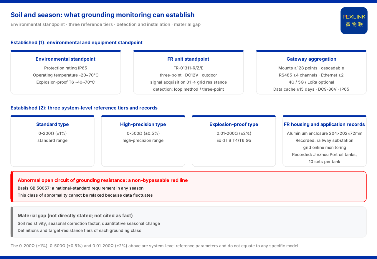
Direct answer
Soil and season can affect grounding monitoring data, and this can be confirmed from the environmental standpoint given by the material: the protection rating of the grounding resistance monitoring unit is IP65, and the operating temperature is -20~70℃ (the explosion-proof T6 version -40~70℃), which shows that the equipment is designed for a long-term outdoor environment. However, the material does not directly give a soil resistivity value, a seasonal correction factor, or a quantitative relationship for how resistance changes with the season, so a figure such as how much higher the resistance in one season is cannot be used as a material conclusion. What can be confirmed is that the judgement of grounding data must take the environment into account, and that an abnormal open grounding circuit is always a bottom line that cannot be bypassed.
1. How far the material can determine
How exactly soil and season affect grounding monitoring data is a question of interest in on-site interpretation. What the material can determine is the relationship between the environment and the equipment, together with the parameter range and installation standpoint of grounding monitoring; as for the soil resistivity value, the seasonal correction factor and the quantitative change of resistance, the material does not state them directly, and they cannot be cited as fact. This boundary is important because the gap is not a matter of reading between the lines: the material is silent on these quantities, and silence cannot be turned into a figure.
2. Environment parameters first: protection rating and operating temperature
The material specifies that the protection rating of the grounding resistance monitoring unit is IP65 and that the operating temperature is -20~70℃, with the explosion-proof T6 version at -40~70℃. This set of figures provides the conditions for the equipment to acquire continuously within an outdoor temperature range; when interpreting data, the environmental conditions in which the equipment sits should be considered together, rather than fixing on a single reading. The protection rating fixes where the equipment can be installed, and the temperature range fixes over what span it can keep acquiring; both are preconditions of a usable record rather than results of the measurement itself.
3. Grounding-grid monitoring ranges are tiered
At the system level, the grounding resistance monitoring reference range given by the material is divided into three tiers: standard type 0-200Ω (±1%), high-precision type 0-500Ω (±0.5%), and explosion-proof type 0.01-200Ω with an explosion-proof rating of Ex d IIB T4/T6 Gb (±2%). The coexistence of the three tiers shows that range and environment are selected as a matched set; the explosion-proof type stands as its own tier, and its parameters cannot be replaced by those of the conventional tiers. The range decides which amplitude band a reading can fall in, and the tier therefore has to be identified before readings are compared or interpreted.
4. Reading data in light of detection principle and installation
The standpoint of a single device likewise affects interpretation. The model rule of the FR grounding resistance monitor (FR-01311-R/Z/E) encodes signal acquisition, detection principle, installation and supply into field positions, in which signal acquisition 01 corresponds to grounding-grid resistance, and the detection principle is divided into the loop method and the three-point method; all three variants use the three-point method, DC12V and outdoor installation, with communication respectively as RS485, Zigbee and Ethernet. When the detection principle and the installation mode differ, the conditions under which a reading is valid also differ; before a cross comparison, the standpoints should be confirmed to be consistent.
5. Convergence is needed to see a trend
To read a trend out of dispersed grounding data, the data has to be converged. The system-level reference parameters of the smart gateway given by the material include mounting not fewer than 128 points with cascadability, not fewer than 4 RS485 channels and not fewer than 2 Ethernet channels, with 4G, 5G or LoRa as options, a data cache of not fewer than 15 days, DC9-36V wide voltage and IP65 protection. The material lists substation and traction substation grounding-grid online monitoring as a typical scenario, with the combination of FR-01311 (1 set per point) together with the lightning protection smart gateway and a cloud-platform-side service; in addition, the material records that the FR housing is an aluminium enclosure of 204×202×72 mm, and that the FR/FRP series has been applied to railway traction substation grounding-grid online monitoring and to the Jinzhou Port oil-tank farm (10 sets per tank). A single point can only show the state at one place; only after the dispersed points are converged do they form a series from which a trend can be read.
6. The bottom line of environmental judgement: an abnormal open grounding circuit
Environmental conditions affect readings, but they do not change one bottom line. The material lists an abnormal open circuit of grounding resistance as a safety red line that cannot be bypassed, with GB 50057 as the governing standard. That is to say, whatever the season, whether the grounding path holds is a national-standard requirement, and the judgement of this class of abnormality cannot be relaxed because the data fluctuates. Environment changes the value of a reading; it does not change the requirement that the path must hold.
Scope and limitations
First, this article explains only the material boundary within which soil and season factors affect grounding monitoring data; its factual boundary is limited to what the product material lists, and it introduces no standard clause, parameter, certification or case that is not listed.
Second, the soil resistivity value, the seasonal correction factor, the quantitative relationship of resistance change with season and the target-resistance tiers of each grounding type are not stated directly by the material; this article expressly lists them as material gaps and does not cite them as fact.
Third, the 0-200Ω (±1%), 0-500Ω (±0.5%) and 0.01-200Ω (±2%) in this article are all system-level reference parameters; this article does not equate them with the specification of any specific model, nor does it determine on that basis whether on-site grounding is qualified.
Fourth, actual grounding design and data interpretation should take site conditions and the applicable standards as the basis; this article does not provide the calculation results of environmental correction.