 FEXLINK Research Institute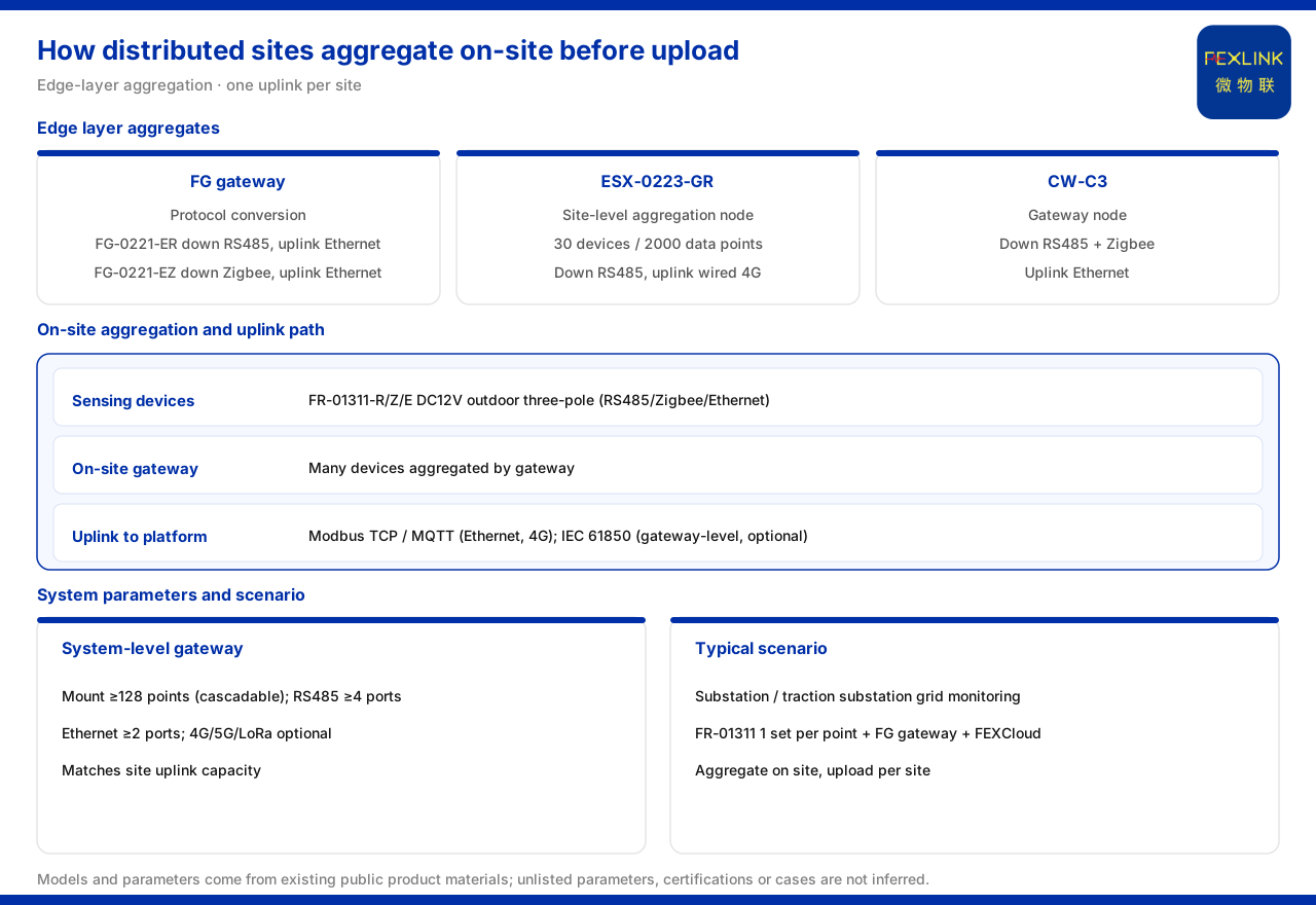
Direct answer
Getting data from dispersed sites to "aggregate within the site before uploading" relies on the aggregation capability of the edge layer. The product knowledge base summarizes the monitoring system as a four-layer architecture of sensing, edge, platform, and application layers, and states that the edge layer consists of the FG, ESX, and CW gateways plus the CX industrial wearable controller and the CC cloud PLC, undertaking protocol conversion, edge computing, and local caching. On specific devices, the FG lightning-protection smart gateway (FG-0221-ER) uses RS485 downlink and Ethernet uplink, the FG lightning-protection smart gateway (FG-0221-EZ) uses Zigbee downlink and Ethernet uplink, the ESX intelligent edge-computing gateway (ESX-0223-GR) has an access capability of 30 devices and 2000 data points with RS485 downlink and wired plus 4G uplink, and the CW industrial gateway (CW-C3) uses RS485 plus Zigbee downlink and Ethernet uplink. The system-level parameters further give a smart gateway mounting of no fewer than 128 points with cascading, no fewer than 4 RS485 channels, no fewer than 2 Ethernet channels, and optional 4G, 5G, or LoRa. The combination for the typical scenario "online monitoring of substation and traction-substation grounding grids" is one FR grounding resistance monitor (FR-01311) per point plus an FG gateway plus the FEXCloud platform.
1. The transmission problem of dispersed sites
Dispersed sites have widely distributed monitoring objects and small per-point data, but the points are geographically separated. If each point were given its own uplink, the number of links would grow with the point count, complicating network planning and operations. The product knowledge base's response is to change the uplink stage from "one link per point" to "one link per site": a gateway inside the site first aggregates the data of several monitoring devices, then sends it to the platform over one uplink path. The devices within a site share one egress, so the unit of link organization changes from the point to the site.
2. The edge layer's position in the architecture
This approach has a place in the architecture. The product knowledge base records that the monitoring system's four-layer architecture is sensing, edge, platform, and application layers; the edge layer consists of the FG, ESX, and CW gateways plus the CX industrial wearable controller and the CC cloud PLC, and undertakes protocol conversion, edge computing, and local caching. Position determines duty: the sensing layer acquires, the edge layer unifies and forwards the data, and the platform and application layers receive the result. In-site aggregation happens at the edge layer, so it is a function of a fixed layer rather than ad hoc processing; the data are normalized there first and then enter the platform.
3. FG: a protocol-converting aggregation foundation
The most basic aggregation is done by the FG gateway. The product knowledge base records that it is a protocol-converting type: FG-0221-ER uses RS485 downlink and Ethernet uplink, and FG-0221-EZ uses Zigbee downlink and Ethernet uplink. The pair shows that the site's downlink determines the model: RS485 devices use FG-0221-ER, Zigbee devices use FG-0221-EZ, and both uplink over Ethernet. Protocol conversion accommodates existing access methods downward and uplinks over Ethernet upward, so several devices share one path.
4. ESX and CW: stronger in-site aggregation nodes
When a site contains many devices, the access capability of the aggregation node becomes the constraint. The product knowledge base records that the ESX intelligent edge-computing gateway (ESX-0223-GR) has an access capability of 30 devices and 2000 data points, with RS485 downlink and wired plus 4G uplink, and that the CW industrial gateway (CW-C3) uses RS485 plus Zigbee downlink and Ethernet uplink. Beyond protocol conversion, the edge-computing gateway also performs edge computing and can handle a certain scale of data access. For dispersed sites, one aggregation node can cover many devices; when the scale exceeds a single unit, extension follows the interface and point relationship, and the access capability directly determines the device scale per site.
5. System-level parameters define the aggregation ceiling
The ceiling of in-site aggregation is defined by the system-level reference parameters. The grounding resistance monitoring system reference parameters record that the smart gateway mounts no fewer than 128 points and can cascade, with no fewer than 4 RS485 channels and no fewer than 2 Ethernet channels, and optional 4G, 5G, or LoRa. These values give three constraints: a single gateway's point scale has a guaranteed lower bound, and cascading extends a larger point count; interface counts determine in-site branches, so insufficient RS485 or Ethernet channels require replanning; the uplink is chosen among 4G, 5G, and LoRa by the site network. Planning should fix the gateway configuration and cascading method by total point count and interface needs.
6. Uplink protocols give the site egress options
After in-site aggregation is complete, the data goes to the platform over an uplink protocol. The communication protocol matrix lists device uplinks of Modbus TCP and MQTT (Ethernet, 4G), plus gateway-level optional IEC 61850. This provides protocol options for the uplink: Ethernet or 4G carries Modbus TCP and MQTT, and where the site has specific protocol requirements, IEC 61850 can be selected. The options mean the egress method is chosen according to site conditions; once chosen, several devices share that egress to the platform.
7. Typical scenarios confirm in-site aggregation
The typical application scenario table writes the combination for "online monitoring of substation and traction-substation grounding grids" as one FR grounding resistance monitor (FR-01311) per point plus an FG gateway plus the FEXCloud platform. The structure is clear: the monitors are placed at the grounding positions for sensing-layer acquisition; the FG gateway serves as the in-site aggregation node, gathering the data of several monitors before uplinking it; and the FEXCloud platform receives the aggregated result. The materials also record that the FR grounding resistance monitor (FR-01311-R/Z/E) is a DC12V outdoor three-electrode unit with communication selectable among RS485, Zigbee, or Ethernet, and can be connected in several sets to cover dispersed grounding-grid points. Multi-point acquisition plus single-site aggregation plus platform reception is the concrete expression of the networking hierarchy of dispersed sites.
8. Reducing in-site aggregation into an ordered sequence
The sequence is as follows. Step one, inventory the site's monitoring points and determine the number and distribution of grounding and other monitored positions. Step two, place monitoring devices by point, such as one FR grounding resistance monitor (FR-01311) per point, to obtain multi-channel data within the site. Step three, determine the downlink according to the monitors' communication options (RS485, Zigbee, or Ethernet). Step four, choose the aggregation node: the FG lightning-protection smart gateway when the site has few devices, and the ESX intelligent edge-computing gateway with access capability and edge computing when the scale is larger. Step five, check the aggregation ceiling against a mounting of no fewer than 128 points, no fewer than 4 RS485 channels, and no fewer than 2 Ethernet channels, to decide whether cascading is needed. Step six, determine the uplink among 4G, 5G, LoRa, and Ethernet according to the site network, and choose the uplink protocol as required. Step seven, connect to the platform, with the FEXCloud platform receiving the site's uplink data. This answers "how the site is normalized internally and how it uplinks through one egress externally."
Scope and limitations
First, this article restates only what the product knowledge base lists, and the factual boundary is limited to the edge-layer composition of the four-layer architecture, the models and interfaces of the FG and ESX gateways, the system-level smart-gateway parameters, the communication protocol matrix, and the typical scenario combination; it introduces no unlisted parameter, certification, or case.
Second, the edge layer's composition from the FG, ESX, and CW gateways plus the CX industrial wearable controller and the CC cloud PLC, its duty of protocol conversion, edge computing, and local caching, and the division of the sensing, platform, and application layers are cited as the product knowledge base lists them.
Third, the downlink and uplink of the FG lightning-protection smart gateway (FG-0221-ER and FG-0221-EZ), the 30 devices and 2000 data points and the downlink/uplink of the ESX intelligent edge-computing gateway (ESX-0223-GR), and the downlink/uplink of CW-C3 are cited as the product knowledge base lists them.
Fourth, the system-level parameters, the device uplink items of the communication protocol matrix, and the one-set-per-point plus gateway plus platform combination for "online monitoring of substation and traction-substation grounding grids" together with the multiple-set access of the FR grounding resistance monitor (FR-01311-R/Z/E) are cited as the product knowledge base lists them.
Fifth, the product knowledge base gives no conversion between in-site aggregation and uplink bandwidth, nor does it expand the concrete drawing of each cascading topology; this article records that boundary and does not infer an unlisted capacity calculation or networking detail from it.
Sixth, this article explains only the networking hierarchy of in-site aggregation and site egress and provides no specific engineering selection or network plan; related conclusions must be confirmed against site network conditions and the project scheme, and the latest product materials and project scheme always prevail.