 FEXLINK Research Institute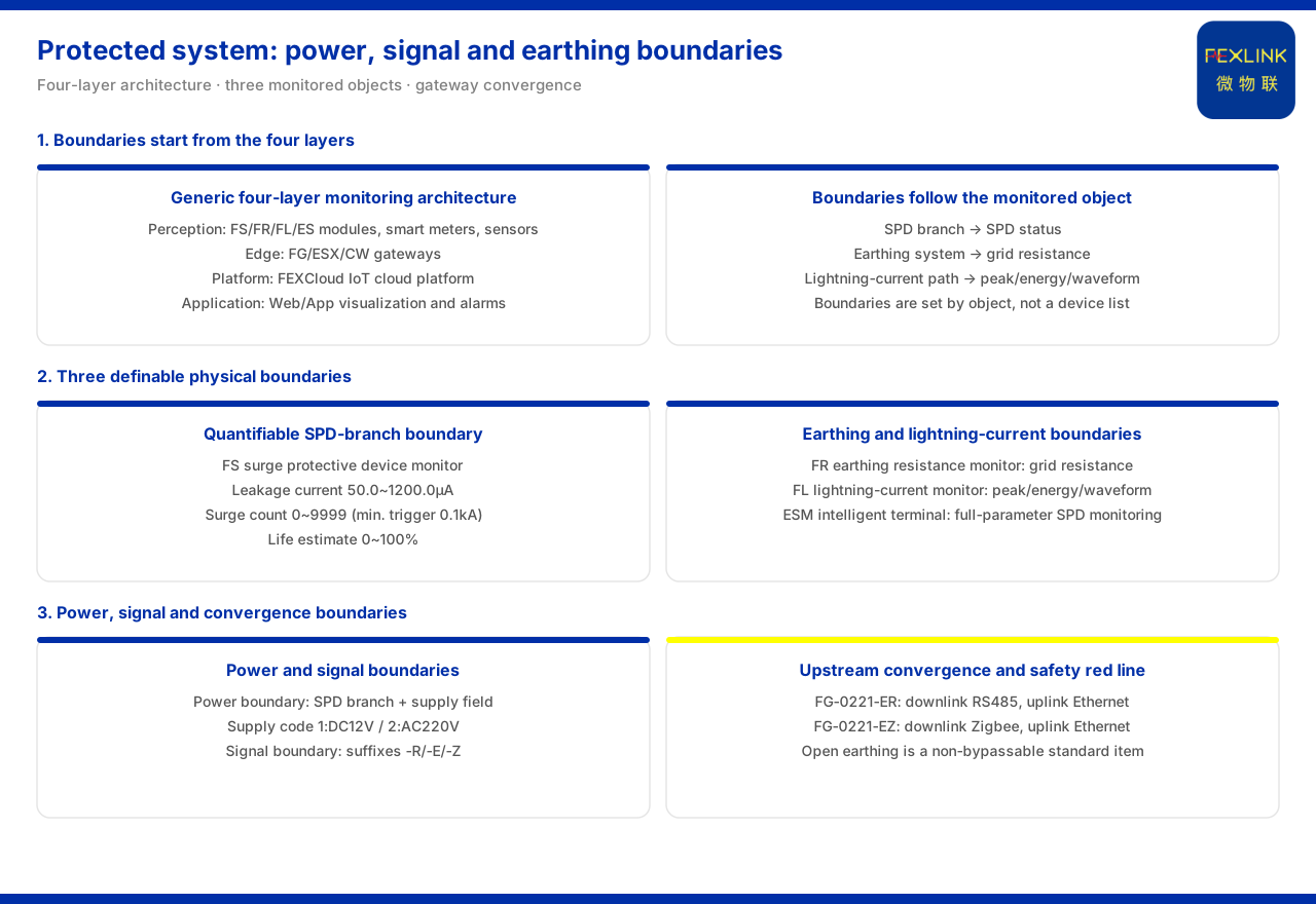
Direct answer
Defining the power, signal and grounding boundaries of a protected system is essentially answering three questions: where lightning energy enters, along which link it propagates, and where it is finally discharged. In its general four-layer architecture, the product knowledge base groups the perception layer's acquisition objects into monitoring modules, smart meters and sensors, the sensor side covering Rogowski coils, NTCs and microamp-level leakage-current sensors. The boundary is therefore not drawn by a device list but determined by the monitored object. Applied to lightning-protection monitoring, the objects split into three definable physical boundaries: the device branch corresponds to the surge protective device state, the grounding system to the grounding-grid resistance, and the lightning-current ingress path to lightning-current peak, energy and waveform. The power boundary is defined by the SPD branch with the supply field; the signal boundary by the communication field with the uplink consolidation node; and the grounding boundary is bound to a non-bypassable standard red line. Stating these three boundaries one by one, then selecting a combination by protected object, is the whole definition work.
Why the boundary starts from the four-layer architecture
The product knowledge base summarises the monitoring system as a four-layer architecture of perception layer, edge layer, platform layer and application layer. The perception layer acquires data from monitoring modules, smart meters and sensors; the edge layer handles protocol conversion and local buffering; the platform layer aggregates and analyses; and the application layer faces specific business. The architecture is the starting point for defining boundaries because it separates "where to acquire" from "how to transmit": the acquisition object determines the physical boundary, and the transmission path the signal boundary. The perception layer lists units such as the FS surge protective device monitor (e.g. FS-00011-R), the FR grounding resistance monitor (e.g. FR-01311-R), the FL lightning current / transient current monitor (e.g. FL-01222-R) and the ES series monitoring modules, showing that the basis for dividing boundaries is the monitored object itself, not the product's form factor or installation position. Only after answering "which section of the monitored object is to be protected" is it meaningful to configure acquisition and transmission for that section.
Power boundary: landing on the SPD branch
On the power side, the boundary lands on the lightning-protection device branch. The product knowledge base specifies that the FS surge protective device monitor monitors elements of that branch such as leakage current, temperature, voltage, lightning-strike counting and lifetime estimation, with key parameters including leakage current from 50.0 to 1200.0 μA, lightning-strike counting from 0 to 9999 counts (minimum trigger 0.1 kA), and lifetime estimation from 0 to 100%. These parameters show that the power boundary is concerned with "how much protection capability the SPD branch has left", not with the whole distribution section. The knowledge base also provides a naming-level basis for power access through the supply field: for lightning-protection products, supply code 1 corresponds to DC12V, 2 to AC220V, 3 to solar power, and 4 to lithium battery. Together the elements and the supply field give the power boundary two checkable dimensions—"what to acquire" and "how to supply power".
Signal boundary: from communication fields to gateway consolidation
On the signal side, the boundary is jointly defined by the communication field and the uplink consolidation node. The product knowledge base specifies that suffix -R corresponds to RS485 and Modbus, -E to Ethernet and MQTT, and -Z to Zigbee and Modbus, and that some products can optionally use 4G. The signal boundary is thus first expressed in "which link is used to send data out". At the end of the link, the FG lightning-protection smart gateway (e.g. FG-0221-ER) provides downlink RS485 or Zigbee and uplink Ethernet through protocol conversion, is powered by DC12V, and can serve as the consolidation node for the signal boundary and uplink aggregation within a protected system. If only the power boundary is defined without the signal boundary, the weak-current and signal links may become an unconsolidated bypass; the product knowledge base lists the gateway as a conversion node between the perception layer and the platform layer precisely to give the signal boundary a clear consolidation position.
Grounding boundary: a loop bound to a standard red line
The grounding boundary is special in carrying a mandatory standard attribute. The product knowledge base specifies that the FR grounding resistance monitor monitors grounding-grid resistance and is listed alongside the SPD branch and the lightning-current ingress path as one of three definable physical boundaries. More critically, abnormal open circuit of grounding resistance is listed as a non-bypassable red line, on the basis of GB 50057. This red line shows that the grounding boundary is not an "optional add-on" but a loop that must be included when defining a protected system: if the grounding-grid resistance cannot be observed, it cannot be proved whether the discharge channel is clear. The grounding system should therefore be treated on a par with power and signal, not left to the end of the scheme.
The lightning-current ingress path must also be defined separately
Besides power, signal and grounding, the lightning-current ingress path is likewise a boundary to be defined. The product knowledge base specifies that the FL lightning current / transient current monitor monitors lightning-current peak, energy and waveform, corresponding to the physical position of the ingress path. The question it answers differs from the first three: the power boundary looks at device state, the signal boundary at the data path, and the grounding boundary at the discharge channel, whereas the ingress path looks at "at what magnitude, and along which path, this particular strike entered". Only by defining this path separately can event magnitude and device state corroborate each other, rather than treating the strike count as the sole evidence of a strike.
Why boundaries are determined by the protected-object scenario
The combination of boundaries is not uniform but varies with the protected object and scenario. In its typical application scenarios the product knowledge base gives two examples: for online grounding-grid monitoring of substations and traction substations it recommends the grounding resistance monitor represented by FR-01311 (one set per point), together with the FG lightning-protection smart gateway and the FEXCloud IoT cloud platform; for oil-tank-area and petrochemical explosion-proof scenarios it recommends a combination of explosion-proof grounding resistance monitoring, the FL lightning current / transient current monitor and the FS surge protective device monitor. Under the same four-layer architecture the boundaries thus differ by scenario: the grounding-grid scenario is dominated by the grounding boundary, while the explosion-proof scenario brings grounding, lightning-current ingress and the SPD branch together.
An operable sequence for defining boundaries
Gathering the clues above into an executable sequence, four steps can be followed. First, answer who the protected object is: the lightning-protection device branch on the distribution side, the grounding system, or the lightning-current ingress path. Second, select the acquisition unit by object: the surge protective device monitor for the device branch, the grounding resistance monitor for the grounding system, and the lightning current / transient current monitor for the ingress path. Third, confirm the supply and communication fields for each unit, so that power access and signal links each take their proper place. Fourth, confirm the signal-side consolidation node and let the gateway aggregate upward to the platform, while checking whether the grounding boundary has been included to satisfy the non-bypassable red line. In this order, the definition answers "which sections the system boundary should cover", not "which product is better".
Applicability and limits
First, this article only restates content listed in the product knowledge base; its factual boundary is limited to the general four-layer architecture, the physical-boundary division of lightning-protection monitoring objects, the general suffixes and supply codes, the gateway's protocol-conversion capability, and the boundary combinations of typical scenarios, and it introduces no unlisted parameters, certifications or cases.
Second, the monitoring elements and parameters of the FS surge protective device monitor (leakage current, lightning-strike counting, lifetime estimation and so on) are cited on the terms listed in the product knowledge base; this article does not infer unlisted configurations from them.
Third, the positioning of the FR grounding resistance monitor for grounding-grid resistance monitoring, of the FL lightning current / transient current monitor for lightning-current peak, energy and waveform, and the protocol-conversion method of the FG lightning-protection smart gateway are all cited on the terms listed in the product knowledge base.
Fourth, the red line for abnormal open circuit of grounding resistance is based on GB 50057 and is a non-bypassable item; this article draws no conclusion on the criterion value or number of points for a specific project.
Fifth, this article only explains how to define the power, signal and grounding boundaries of a protected system and provides no selection, setting or configuration calculation for a specific project; relevant conclusions must be determined with on-site conditions and the project scheme.
Sixth, this article does not commit to any specific project's selection result or on-site performance, which remain subject to the latest product documentation and project scheme.