 微物联研究院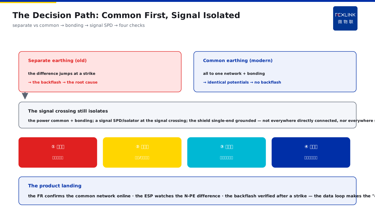
Direct Answer
Experienced engineers habitually drive separate electrodes for lightning-protection earthing, electrical earthing and electronic-system earthing, while data centers insist on tying everything to one earthing busbar — who is right? The answer: modern lightning protection (GB 50343 / IEC 62305) advocates common grounding — connecting the lightning protection, electrical protection, electronic systems and shielding all to the same earthing network, then eliminating the potential differences between them through bonding; with separate electrodes, the earth potential rises back during a strike, forming a dangerous earth-potential backflash, which is actually a common root cause of electronic-equipment damage.
At a park, following the old habit, "lightning-protection separate earthing + electronic-system separate earthing" was done with the spacing also widened. After one strike, the equipment in the computer room was damaged in batches; the investigation found that the potential difference between the two earth grids instantly reached more than a kilovolt, and the backflash current poured into the equipment through the electronic-system earth conductor. After switching to a common earthing network + bonding, the same storms caused no more damage. The key distinction: separate electrodes form an earth-potential backflash under a strike — the potential difference between the two earth grids instantly jumps, and the backflash current pours into the equipment; common grounding connects all systems to one network and uses bonding to flatten the potential differences, which is the "antidote" to electronic-equipment damage.
Why:
- The earth-potential backflash mechanism: the potential difference between separate grids jumps at the strike instant, and the backflash current enters the equipment;
- The composition of the common earthing: lightning/electrical/electronic/shielding all connected to the same earthing network;
- The value-setting logic: take the low value per the lightning-protection requirement, and the other systems share that network;
- The bonding: flattens the potential differences inside the common network, keeping the equipment potentials identical.
Key insight: "Separate electrodes fear the backflash; common grounding flattens the potential — the potential difference between two grids jumps instantly under a strike and the backflash pours into the equipment; the common earthing network + bonding eliminates the potential differences, which is exactly why the data center insists on common grounding."
At a factory the construction insisted on grounding the lightning protection and the equipment separately, and the acceptance passed; in the first thunderstorm the control board was burned and the earth-potential backflash damaged two devices. Lesson: separate earthing does not equal safety — the potential difference between the two grids under a strike is the backflash source; common earthing + bonding is the system-level answer.
Overview: run "the backflash mechanism → the common-earthing composition → the bonding → the places still needing isolation" as one system-level cognition. "Common grounding or separate electrodes" is the most common earthing argument on site: the old experience likes to drive separate piles for each system, while the modern standard advocates common grounding. The essence of the disagreement lies in a different understanding of the "earth potential" behavior under a strike — between separate grids a huge potential difference is formed at the strike instant, creating the backflash; the common earthing network + bonding "flattens" this potential difference. The four layers are unfolded below.
An "two wells" analogy for the two grids: think of separate earthing as two buildings each digging its own well — they are fine separately in normal times; at a strike, the water level of the lightning-protection well rises instantly, while the water level of the electronic-system well stays still, and the height difference between the two wells (the potential difference) is the "water flow" of the backflash, backing up into the equipment along the connecting pipes (the earth/signal conductors). Common earthing merges the two wells into one large pool, and at a strike the water level rises together — no height difference, no backflow; the bonding is laying a few more connecting pipes in the large pool to ensure the water level is identical in any corner. The two-well analogy: separate earthing = two wells with a jumping water-level difference under a strike and backflow through the pipes (the backflash); common earthing = one large pool where the level rises together; the bonding = more connecting pipes ensuring an identical level in any corner.
1. The Earth-Potential Backflash: The Hidden Danger of Separate Earthing
Step one: the problem of separate earthing is not in normal times but at the strike instant.
The mechanism of the backflash:
- The lightning current enters the earth through the separate lightning-protection grid;
- The potential of that grid rises instantly;
- A huge potential difference with the electronic-system grid;
- The backflash current enters the equipment along the earth/signal conductors.
Why it is invisible in normal times:
- The potential difference is tiny in normal times;
- The equipment works normally without anomalies;
- The potential difference only shows at the strike instant;
- So a "passed acceptance" still results in strike damage.
The consequences of the backflash:
- The insulation of the electronic equipment breaks down;
- The boards/ports damaged in batches;
- The fault misjudged as a quality problem;
- The root cause in the grid potential difference.
Key insight: "The hidden danger of separate earthing is at the strike instant — the potential of the lightning-protection grid rises instantly, forming a huge potential difference with the electronic-system grid, and the backflash current pours into the equipment; invisible in normal times, exposed only at the strike, and a 'passed acceptance' still results in damage."
2. Common Grounding: Composition and Value-Setting Logic
Step two: common grounding connects all systems to one network, with the value set per the lightning-protection requirement.
The composition of the common earthing:
- Lightning-protection earthing;
- Electrical-protection earthing;
- Electronic-system earthing;
- Shielding/bonding;
- All connected to the same earthing network.
The value-setting logic:
- Take the low value per the lightning-protection requirement (e.g., ≤1Ω);
- The other systems share that network;
- No separate grids built;
- Potential consistency is the goal.
Why the data center insists:
- Electronic equipment is the most sensitive to the potential difference;
- The common network + bonding keeps the potentials identical;
- No backflash path under a strike;
- The damage probability drops sharply.
Key insight: "Common grounding connects the lightning/electrical/electronic/shielding to one network, with the resistance set low per the lightning-protection requirement; the data center insists on it because the electronic equipment is the most sensitive to the potential difference, the common network has no backflash path, and the damage probability drops sharply."
3. The Bonding: Flattening the Potential Differences in the Network
Step three: the common earthing is the foundation, and the bonding truly flattens the potential differences.
The role of the bonding:
- Pulling the potentials of all points in the network level;
- Eliminating the potential differences between the equipment;
- At a strike the potentials rise together;
- No potential difference means no backflash current.
The relation to the common earthing:
- The common earthing provides "the same reference";
- The bonding eliminates the "residual differences";
- Both are indispensable;
- Handled centrally at the boundaries (relating to KD-0207).
The engineering practice:
- The metal pipes/cables entering the building bonded;
- The equipment shells/cabinets connected into the bonding;
- Key weak-current positions strengthened;
- The bonding-conductor specifications per the standard.
Key insight: "The common earthing is the foundation and the bonding is the finishing touch — the bonding pulls all points in the network level, and at a strike they rise together, with no potential difference meaning no backflash; the in/out pipes, the equipment shells and the cabinets are all bonded, with the weak-current positions strengthened."
4. When Isolation Is Still Needed: SPD at the Signal Crossing
Step four: common does not mean connecting everything directly; the signal crossing still needs "isolation".
Why isolate at the signal positions:
- The signal systems have different potential references;
- Direct connection introduces the ground loop;
- The ground loop brings noise/interference;
- An SPD/isolator transition is needed.
How to isolate:
- A signal SPD at the crossing (relating to KD-0164/0208);
- Optocoupler/isolation-transformer isolation;
- The shield layer grounded at one end;
- The isolation and the bonding used together.
The judging points:
- The power system: common + bonding;
- The signal system: an SPD isolation at the crossing;
- The shield layer: single-end grounding against the loop;
- Not everywhere directly connected, nor everywhere separated.
Key insight: "Common does not mean connecting everything directly — the signal crossing needs 'isolation' (a signal SPD/optocoupler/isolator), and the shield layer is single-end grounded against the loop; the power common + bonding, the signal crossing SPD, and the judgment is made by system."
Four checks to land "common" in construction and acceptance: writing "common earthing" on the drawing is easy; the on-site implementation is verified by four points: one, the earthing network — confirm that the lightning, electrical and electronic systems are all connected to the same network/busbar, not each pulling its own pile; two, the bonding — the in/out pipes, the equipment shells and the cabinets bonded, with the key positions strengthened per the standard; three, the test points — reserved on the common network so the resistance can be re-measured (the FR online); four, the post-storm check — after a thunderstorm, verify the N-PE potential difference and the equipment states, and whether a backflash happened is spoken by the data. The four checks: the earthing network (all to one network, not separate piles) → the bonding (pipes/shells/cabinets bonded) → the test points (re-measurable on the common network) → the post-storm check (the N-PE difference and the equipment states spoken by the data).
5. Product Implementation: Common Grounding Made Visible
WeiWuLian products bring the common-earthing system into verifiable monitoring:
- The FR Earth-Resistance Monitor: the resistance of the common network confirmed online;
- The ESP Zero-Voltage Monitor: the N-PE potential difference continuously monitored;
- The system view: the earthing/potential difference/equipment states on one screen;
- The data loop: after a strike, verify whether a backflash happened.
The design principle in one sentence: "Separate electrodes fear the backflash; common grounding flattens the potential — the FR monitors the common-network resistance and the ESP watches the N-PE potential difference; the data loop turns the 'earthing argument' into a visible engineering fact."
Three "plausible" arguments for separate earthing and the counter-evidence: the arguments for separate earthing on site are common in three forms, all counterable. Argument one, "separate earthing does not interfere" — counter: the interference comes from the potential difference, and the common network with identical potentials does not interfere; argument two, "the separate resistance is easier to achieve" — counter: the lightning-protection grid resistance already needs to be low, and the other systems share it, with no need for each to reach the standard; argument three, "the old projects all did it" — counter: the old practice is a legacy of the old concept, and GB 50343 / IEC 62305 already clearly advocate common + bonding. The common problem of the three arguments: they only see the normal times, not the potential-difference behavior at the strike instant. The three arguments and the counter-evidence: no interference (counter: the interference comes from the potential difference), the resistance easier (counter: sharing is enough, no need for each to reach the standard), the old projects all did it (counter: a legacy, the standard already advocates common) — the common problem: only seeing the normal times, not the strike instant.
6. Common Understanding Misjudgments
- "Separate earthing for each system is safer": wrong. The potential difference between the separate grids forms the backflash under a strike, which is the root cause of the damage.
- "Common earthing interferes": unproven. Common + bonding keeps the potentials identical; the interference comes from the potential difference, not from the common earthing.
- "Passed acceptance means no damage": wrong. The backflash happens at the strike instant and cannot be measured in normal times; the online monitoring must watch the storm period.
- "Bonding only in the computer room": wrong. The in/out pipes and the equipment shells must be bonded, with the key positions strengthened.
- "Everywhere common = everywhere directly connected": wrong. The signal crossing uses an SPD/isolator transition, and the shield layer is single-end grounded.
Scope and Limitations
This article explains the system-level trade-off between common earthing and separate electrodes (the backflash mechanism, the common-earthing composition, the role of the bonding, the signal isolation), applicable to earthing-design and acceptance-argument judgments. The specific resistance limits and bonding practices follow GB 50343-2012 and GB/T 50065-2011; this article explains only the system logic. All cases are anonymized (a park/a factory) and do not refer to any specific customer.