 FEXLINK Research Institute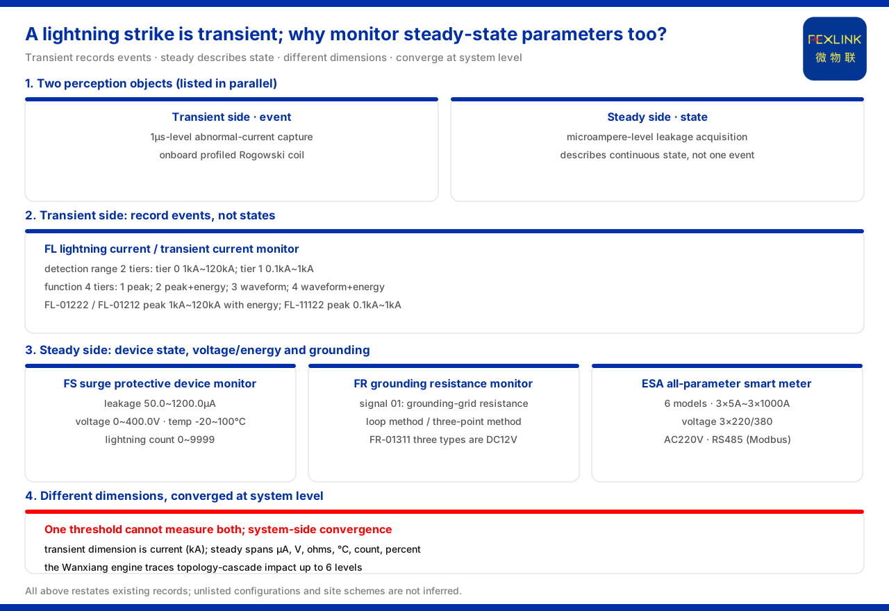
Direct answer
A lightning strike is itself a transient event, yet a monitoring system still acquires steady-state electrical parameters at the same time, because these two classes of parameter answer different questions. Transient parameters answer "how large this impact was and in what shape it occurred", while steady-state parameters answer "what state the device and circuit are in at this moment and whether they have degraded". In its core sensor technology section, the product knowledge base lists the 1μs-level abnormal-current capture of the onboard profiled Rogowski coil and the microampere-level leakage-current acquisition as two different perception objects in parallel, the former facing lightning and transient events and the latter facing continuous leakage states; in the general four-layer architecture of the monitoring system, the perception layer also lists objects such as the FS surge protective device monitor (e.g. FS-00011-R), the FR grounding resistance monitor (e.g. FR-01311-R), the FL lightning current / transient current monitor (e.g. FL-01222-R) and the ESA all-parameter smart meter (e.g. ESA-22111-R) at the same time. Monitoring only transients can reconstruct the impact process but cannot see whether the device has degraded; monitoring only steady states can reveal trends but cannot catch transient events. Only the two classes in parallel can answer both "what happened" and "is it still usable now".
1. Where the distinction between transient and steady comes from
One boundary must be stated first: the product knowledge base gives neither a terminological definition of "transient parameters" and "steady-state parameters" nor an explicit division of time scales. The distinction between the two is generalised from the relevant sections. The core sensor technology section lists the 1μs-level abnormal-current capture and the microampere-level leakage-current acquisition as two classes of perception; the lightning current / transient current monitor section faces lightning and transient currents, while the surge protective device monitor, grounding resistance monitor and all-parameter smart meter sections face continuous quantities such as leakage current, voltage, grounding resistance and electric energy. The product knowledge base does not express the two classes as the same quantity but records them separately by perception object. The distinction comes from the physical object, not from a range that can be adjusted at will.
2. The transient side: record events, not states
The landing point on the entry side is lightning current / transient current monitoring. The product knowledge base specifies that the model rule of this class of monitor is formed by detection range, channel count, function, installation method and power supply in the body segment, with communication listed separately. The detection range has two tiers, 0 covering 1kA to 120kA and 1 covering 0.1kA to 1kA; the function has four tiers, 1 for peak, 2 for peak plus energy, 3 for waveform and 4 for waveform plus energy. In the model table, the FL-01222 (indoor) and FL-01212 (outdoor) both have a peak range of 1kA to 120kA and support energy, while the FL-11122 (indoor) has a peak range of 0.1kA to 1kA and does not support energy; all three are supplied at AC220V. The dimension of this class of data is current, recording the magnitude and shape of one event, so it falls on the transient side and cannot describe the device's continuous state between two events.
3. The steady side one: device state and leakage current
One landing point on the steady side is the surge protective device monitor. The product knowledge base gives its key parameters: leakage current 50.0 to 1200.0μA (±10μA), voltage 0 to 400.0V (±0.1V), temperature -20 to 100℃ (±1℃), lightning count 0 to 9999 times (minimum trigger 0.1kA) and lifespan estimation 0 to 100%. Among these, leakage current, voltage, temperature and lifespan estimation describe the continuous state of the device; although the lightning count relates to lightning, it records a number of times, not the strength of each event, so it is a body-state quantity and cannot replace transient-side event acquisition.
4. The steady side two: voltage, energy and grounding
The steady side also includes voltage, electric energy and grounding resistance. The product knowledge base records that the ESA all-parameter smart meter has 6 models in total, covering ESA-22111-R to ESA-22161-R, with current specifications of 3×5A to 3×1000A, voltage 3×220/380, support for meter monitoring, 2 digital inputs and 1 relay output, supplied at AC220V across the whole series with OLED display and RS485 (Modbus) communication, and without phase and harmonic monitoring; it acquires steady-state voltage and energy-type parameters. The grounding side is carried by the FR grounding resistance monitor, in whose model rule signal acquisition 01 means the grounding-grid resistance, detection principle 2 is the loop method and 3 the three-point method, and installation method 1 is outdoor and 2 indoor; in the model table, the grounding monitor's FR-01311-R, FR-01311-Z and FR-01311-E are all DC12V, outdoor-installed and three-electrode measured, communicating over RS485, Zigbee and Ethernet respectively, with an aluminium housing 204×202×72mm.
5. Different dimensions, criteria cannot be applied across
A direct reason the two classes must be parallel rather than merged is that their dimensions differ. The dimension on the transient side is current, up to the kiloampere level; the dimensions on the steady side include microampere, volt, ohm, degree Celsius, count and percentage. Different dimensions mean that the same threshold cannot measure both classes of parameter: a transient event is judged by "how large this one was", and a steady state by "whether it deviates from normal at this moment". Writing the two classes into one criterion, or using one quantity to replace the other, loses one class of information.
6. System side: risks that both parameter classes point to
The meaning of parallel acquisition must ultimately land on the system side. The general four-layer architecture of the monitoring system describes the perception layer as "FS/FR/FL/ES series monitoring modules, smart meters and sensors (Rogowski coils, NTCs, microampere-level leakage-current sensors)", that is, the same perception layer contains both transient and steady acquisition; on the system-judgment side, the topology-cascade impact calculation capability of the Wanxiang engine can trace up to 6 levels of topology-cascade impact, used to assess the system-level risk to which the two classes of parameter jointly point. That is, transient data shows through which segment the impact entered and at what magnitude, while steady data shows whether the receiver and the discharge channel can still work; only when the two converge at system level can it be judged whether it will propagate to the next level.
7. Reducing parallel monitoring to a checking order
Putting the above together, "why separate monitoring is needed" reduces to an operable checking order. First, ask whether this monitoring answers an event question or a state question: to reconstruct the lightning process, the landing point is transient-side lightning current / transient current monitoring. Second, to judge whether a device is still usable, the landing point is steady-side surge protective device state monitoring, checking element coverage by leakage current, voltage, temperature and lifespan estimation. Third, to judge the energy-reception and discharge channel, the landing point also includes grounding resistance monitoring. Fourth, return to the system side and check, by topology position and cascade impact, which layer each class of parameter belongs to. By this order, parallel monitoring answers "what each class of parameter solves", not "which class of parameter is more important".
Scope and limitations
First, this article restates only what the product knowledge base lists, with the factual boundary limited to the core sensor technology, the general four-layer architecture of the monitoring system, the model rules and key parameters of the lightning current / transient current monitor, the surge protective device monitor, the grounding resistance monitor and the all-parameter smart meter, and the records on topology-cascade impact, introducing no unlisted parameters, certifications or cases.
Second, the onboard profiled Rogowski coil's 1μs-level abnormal-current capture and the microampere-level leakage-current acquisition as two classes of perception object, and the two detection-range tiers, four function tiers and model-table installation environment, power supply and energy support of the lightning current / transient current monitor, are cited per the product knowledge base.
Third, the key parameters of the surge protective device monitor and the current specifications, voltage, communication and element range of the all-parameter smart meter are cited per the product knowledge base.
Fourth, the model rule and the parameters and housing dimensions of the FR-01311 types of the grounding resistance monitor, and the topology-cascade impact tracing up to 6 levels, are cited per the product knowledge base; this article draws no conclusion about the criterion values of any project.
Fifth, the product knowledge base gives no terminological definition or time-scale division of "transient parameters" and "steady-state parameters"; this article transcribes this boundary.
Sixth, this article only explains why transient and steady-state parameters need parallel monitoring and provides no specific project selection, threshold setting or configuration calculation; the relevant conclusions must be confirmed with site conditions and the project solution. This article constitutes no commitment about the selection result or field behaviour of a specific project; actual conditions are subject to the latest product material and project solution.