 FEXLINK Research Institute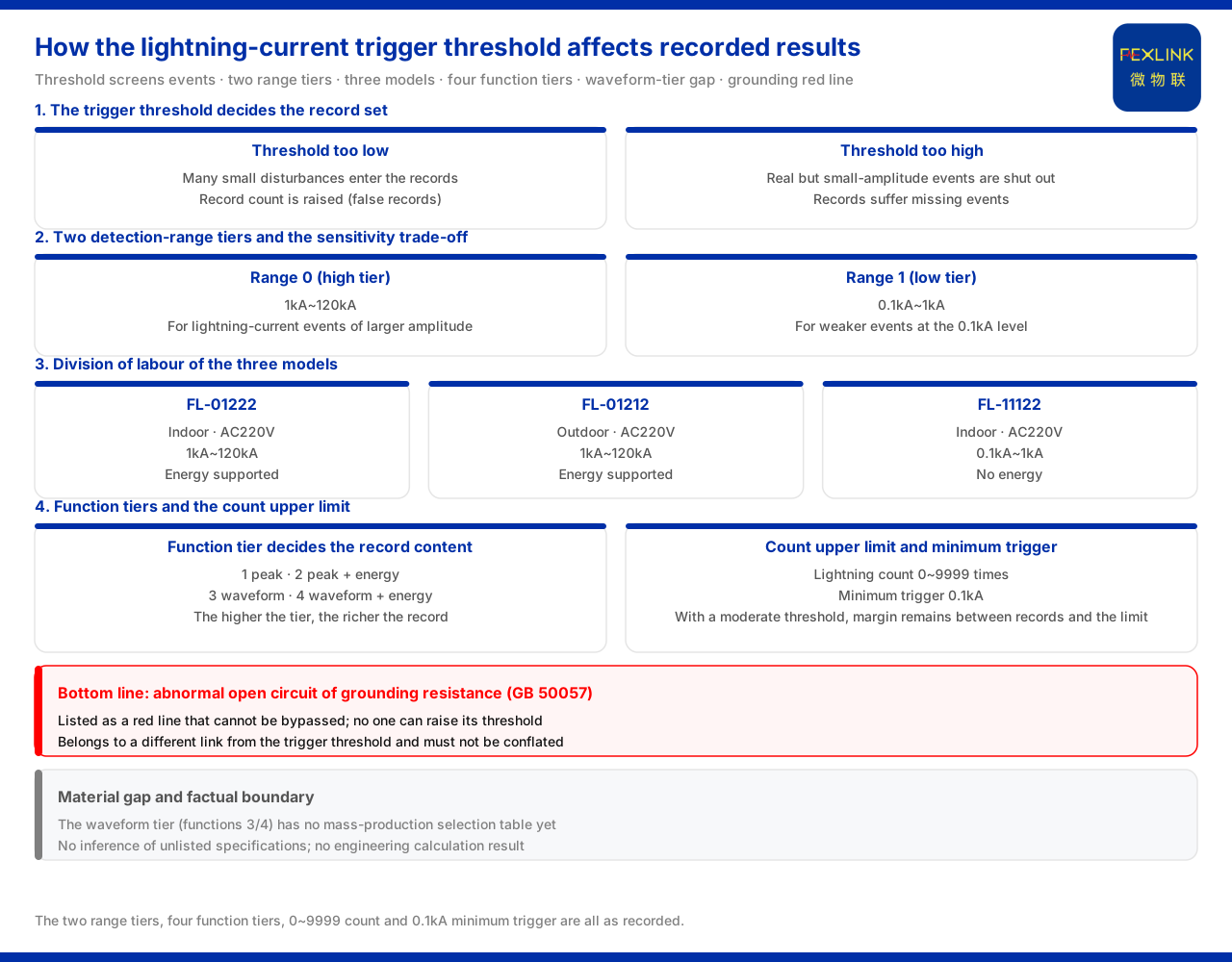
Direct answer
The threshold setting of lightning-current monitoring directly determines which events are recorded. The product material gives two related conventions: first, the lightning count of the FS surge protective device monitor (e.g. FS-00011-R) is 0 to 9999 times with a minimum trigger of 0.1kA; second, the FL lightning current / transient current monitor (e.g. FL-01222-R) provides two detection ranges, 1kA to 120kA and 0.1kA to 1kA. A threshold set too low lets a large number of small disturbances enter the records and raises the number of records; a threshold set too high misses real but small-amplitude events. The trigger threshold is therefore the result of a trade-off between "missing records" and "false records", not a value that can be set at will. Understanding this is the precondition for configuring lightning-current monitoring parameters.
1. The trigger threshold decides the record set
Lightning-current monitoring does not make a continuous, undifferentiated record of current; it screens events by threshold. The material places this logic in two places: first, the minimum trigger of the surge protective device monitor is 0.1kA, and current below that threshold is not counted as a lightning event; second, the lightning current / transient current monitor uses a detection-range position to distinguish the high and low range tiers. The threshold and the range together determine "which events enter the record and up to how large they are recorded".
Understanding the threshold as a screening gate makes its two sides clear: set the gate low, and many events come in, among which a large amount of background disturbance is inevitably mixed; set the gate high, and few events come in, but a real weak lightning strike may also be shut out. Whether the recorded result is usable depends on whether this gate matches the monitoring purpose.
2. The two detection-range tiers and the sensitivity trade-off
The model rule of the material encodes the detection range into a position: 0 corresponds to 1kA to 120kA and 1 corresponds to 0.1kA to 1kA; the detection range together with the function position decides the trigger threshold and the record content. The two range tiers correspond to different sensitivity orientations: the high-range tier faces lightning-current events of larger amplitude, while the low-range tier points to weaker events at the 0.1kA level.
The low range is not a scaled-down version of the high range but another range facing a different observation purpose. The three models given by the material embody this division of labour, as follows:
| Model | Installation environment | Supply | Peak range | Energy support |
|:--|:--|:--|:--|:--|
| FL-01222 | Indoor | AC220V | 1kA~120kA | Supported |
| FL-01212 | Outdoor | AC220V | 1kA~120kA | Supported |
| FL-11122 | Indoor | AC220V | 0.1kA~1kA | No |
It can be seen that the same series distinguishes the high and low ranges through the detection-range position, and the low-range model is used for more sensitive recording of events at the 0.1kA level. Which tier to choose depends on whether one cares about statistics of strong lightning strikes or the capture of weak events.
3. The function tier decides the record content
Besides the detection range, the function position also enters the model rule: 1 is peak, 2 is peak plus energy, 3 is waveform, and 4 is waveform plus energy. The function tier answers "to what extent it records", while the detection range answers "within what interval events are recorded"; the two together decide the trigger threshold and the record content.
From peak to waveform plus energy, the richness of the record increases. Recording only the peak gives the amplitude; adding energy allows further observation of the energy convention of the event; entering the waveform tier extends the record content to the waveform; waveform plus energy covers both at once. The choice of function tier should match the question of concern: if only whether there was a lightning strike and the amplitude need to be judged, the peak tier suffices; if more complete event characteristics are needed, a higher function tier must be requested.
4. The matching of outline and installation
The material also gives the outline information of this monitor: it uses a lightning-monitoring enclosure in two colours, white and black; the outdoor model FL-01212 uses an aluminium enclosure with dimensions 204×202×72mm. The installation environment and enclosure form match the detection range and the installation-method position. This shows that, beyond the range and function, the installation environment also needs confirmation; the indoor and outdoor models each have a corresponding configuration in enclosure and protection and cannot be selected in isolation from the installation scenario.
5. The relation between threshold and count upper limit
Beyond the threshold there is a parameter matched with it: the count upper limit. The material gives the lightning count of the surge protective device monitor as 0 to 9999 times with a minimum trigger of 0.1kA. The count upper limit decides how many events can be recorded at most within one operating cycle, and the minimum trigger decides the admission line of an event. The two act together on the recorded result: if the threshold is too low, the number of events grows faster and the count upper limit is more easily approached; if the threshold is moderate, a reasonable margin remains between the number of records and the limit.
This relation also hints that the minimum trigger of 0.1kA corresponds to the 0.1kA to 1kA of the low-range tier, showing that "0.1kA" is an explicit low-end reference point in the material. It decides which lightning events are recorded and to what extent the records reflect the real lightning activity.
6. The position in the perception layer
Lightning-current monitoring is not an independent system but a component of the perception layer. The general four-layer architecture of the monitoring system given by the material puts the lightning-current monitoring module in the perception layer, alongside other monitoring modules, smart meters and sensors; after protocol conversion, edge computing and local caching at the edge layer, the perception-layer data is uploaded to the platform layer and the application layer. Because the perception layer uplinks only the events that pass the threshold, the trigger threshold actually decides the set of data events entering this chain.
The meaning of understanding this position is that the threshold is not merely a device parameter; it also affects what the upper layer can see. If the threshold is set improperly, the upper layer receives a biased event set — either too dense or too sparse. The threshold configuration should therefore be considered together with the subsequent alarm, statistics and analysis purposes.
7. The current limit of the selection convention
One known information gap should be pointed out. In the known-information-gap entry of its appendix, the material states explicitly that the lightning current / transient current monitor models of the waveform tier (functions 3 and 4) do not yet have a mass-production selection table. Therefore, regarding the trigger and recording capability involving waveform functions, there is currently a limit in the selection convention — the mass-production models listed by the material are concentrated in the peak and peak-plus-energy tiers, and the waveform tier has no corresponding mass-production model available for selection. When waveform recording is needed in planning, this limit should be taken as a precondition.
8. Bottom line: an abnormal open circuit of grounding resistance
The threshold configuration of lightning-current monitoring and the grounding bottom-line judgement belong to different links. The material lists "an abnormal open circuit of grounding resistance" as a red line that cannot be bypassed, whose threshold no one can raise, with GB 50057 as the basis standard. That is, lightning-current monitoring can adjust the threshold and range by scenario, but this national-standard red line of grounding cannot be relaxed, and the two must not be conflated. The trade-off of the trigger threshold is parameter configuration, and the grounding red line is a standard constraint; the boundary is clear.
Scope and limitations
First, this article explains only how the trigger threshold and sensitivity of lightning-current monitoring affect the recorded result; the factual boundary is limited to what the product material lists, and it introduces no standard clause, parameter, certification or case not listed.
Second, the two detection-range tiers, the four function tiers, the 0 to 9999 count and the 0.1kA minimum trigger are all existing records of the material; this article does not infer the specifications of unlisted models from them, nor does it prejudge the lightning-strike statistics of any specific site.
Third, the statement that the waveform tier does not yet have a mass-production selection table is limited to the known information gap recorded by the material; this article does not extend to infer the release time or technical indicators of that tier.
Fourth, the final setting of the trigger threshold and range must be verified in conjunction with the monitoring purpose and on-site conditions; this article provides no engineering calculation result.