 FEXLINK Research Institute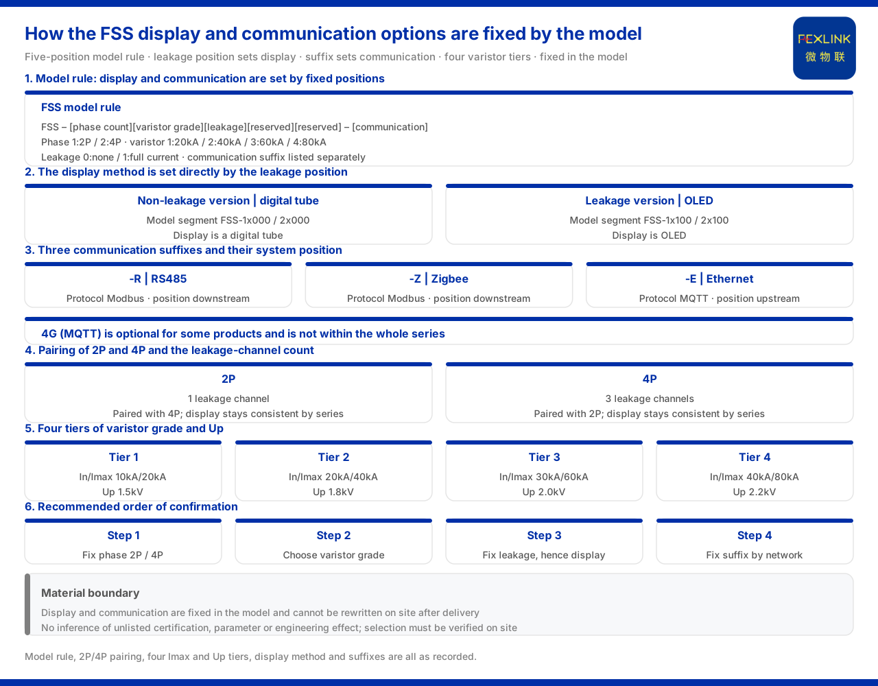
Direct answer
The display and communication options of the FSS intelligent surge protective device (e.g. FSS-11000) are not add-ons to be ticked by experience when ordering but are decided by fixed positions in the model rule. The model rule of the material for the FSS is FSS–[phase count][varistor grade][leakage current][reserved][reserved]–[communication]: the phase-count position distinguishes 2P from 4P, the varistor-grade position distinguishes four tiers of Imax, and the leakage-current position distinguishes "no leakage current" from "full current". The leakage-current position also decides the display method — the non-leakage version uses a digital tube, the leakage version uses OLED. Communication is listed separately in the tail section of the model; the whole series is supplied at AC220V, all support RS485 (-R), and Zigbee (-Z) or Ethernet (-E) can be selected by suffix. Therefore, determining display and communication is in effect confirming two things: the leakage-current position and the communication suffix.
1. The display method is decided directly by the leakage-current position
The material binds the display method to the leakage-current configuration: the non-leakage version (model segments 1x000 and 2x000) uses a digital-tube display, while the leakage version (model segments 1x100 and 2x100) uses OLED. This means that the display method has no independent option; it is decided by the numbering entry of the leakage-current position. If the site needs to read leakage current, the selection necessarily enters the leakage version and thereby also accepts OLED display; if the non-leakage version is chosen, the display is a digital tube.
Understanding the display as a "by-product of the leakage-current position" avoids a common misconception: treating display and leakage current as two switches that can be freely combined. What the material gives is a one-to-one correspondence, not free pairing. Therefore, as soon as it is determined whether leakage current is needed, the answer to the display method is determined, and no separate decision is needed.
From the selection-process point of view, this binding also simplifies the decision.
2. The three tiers of communication suffix
The communication field is listed separately in the tail section of the model; the whole series supports RS485 (-R), and Zigbee (-Z) and Ethernet (-E) are selected by suffix. The material further clarifies in the general suffix definitions that -R is RS485 (Modbus), -E is Ethernet (MQTT) and -Z is Zigbee (Modbus), with 4G (MQTT) reserved as optional for some products.
This set of correspondences shows that the communication option does not change the main functions of the unit but only decides the networking method for upstream and downstream. The communication suffix must therefore correspond to the network conditions actually available on site, not merely to whether the product side supports it. If the site has only serial wiring, -R is the natural choice; if an Ethernet link is already present, -E is more convenient for direct uplink; if wiring is difficult and short-range wireless networking is needed, -Z can be considered.
3. The paired relation of 2P and 4P
The parameter table of the material lists the 2P and 4P models in pairs: the digital-tube segment runs from FSS-11000/21000 to FSS-14000/24000, and the OLED (with leakage current) segment from FSS-11100/21100 to FSS-14100/24100, with the parts before and after the slash corresponding to 2P and 4P respectively. Under the same varistor and leakage-current combination, 2P and 4P appear in pairs, and the display method stays consistent between them by series.
The difference is concentrated in the phase count and the number of leakage-current channels: 4P has 3 leakage channels and 2P has 1. That is, within the leakage version, 4P can cover more channels of leakage-current monitoring than 2P. During selection one should first look at whether the protected circuit is single-phase or three-phase and how many leakage channels need monitoring, then decide the phase-count position, rather than choosing display or communication first.
4. The four tiers of varistor grade and Up
The varistor-grade position divides Imax into four tiers, corresponding to different Up: 10kA/20kA corresponds to 1.5kV, 20kA/40kA to 1.8kV, 30kA/60kA to 2.0kV, and 40kA/80kA to 2.2kV, with the highest tier's Imax being 80kA.
The display and communication options are independent of the varistor parameters: the varistor grade decides the combination of In/Imax and Up, while display and communication are decided by the leakage-current position and the suffix. The two kinds of field each govern a segment, and both must be confirmed separately during selection.
5. The place of communication in the system protocol matrix
The communication suffix is not an isolated rule; it falls within the communication protocol matrix of the material. The matrix stipulates that the device downstream protocols are Modbus RTU (RS485), Zigbee (Modbus) and LoRa, that the upstream protocols are Modbus TCP and MQTT (Ethernet, 4G), and that IEC 61850 is optionally available at gateway level. The -R, -Z and -E suffixes of the FSS fall respectively within this downstream/upstream system.
This shows that the communication option has a system-level basis: when -R or -Z is chosen, data enters the downstream system dominated by Modbus; when -E is chosen, it uplinks to Modbus TCP or MQTT over Ethernet. Clarifying the in-station networking and the uplink method first and then working back to the suffix is the more reliable order. A suffix chosen this way can both connect and access the existing platform and gateway.
The relation between the three suffixes and the protocol system can be summarised as follows:
| Suffix | Communication | Protocol | System position |
|:--|:--|:--|:--|
| -R | RS485 | Modbus | Downstream |
| -Z | Zigbee | Modbus | Downstream |
| -E | Ethernet | MQTT | Upstream |
The material also notes that 4G (MQTT) is optional for some products and is a reserved uplink method. The three tiers in the table are suffixes selectable across the whole FSS series, whereas 4G is not within the whole-series scope and cannot be assumed available during selection.
6. The recommended order of confirmation
Bringing the above together, the display and communication of the FSS can be confirmed in four steps: first, determine the phase count, whether 2P or 4P; second, determine the varistor grade, chosen from the four Imax tiers; third, determine whether leakage current is needed, thereby also determining the display method; fourth, select the communication suffix according to the on-site network conditions. The first three steps decide the model body and the fourth decides the tail section, in a clear order.
These four steps also correspond to a discipline: display and communication are not items that can be specified separately from the model body; they are respectively the result of the leakage-current position and the suffix. Fixing the decision order avoids such combination errors as "OLED chosen but no leakage current" or "the suffix does not match the on-site link".
It should be emphasised again that display and communication belong to two mutually non-interfering fields: display is decided by the leakage-current position, communication by the suffix, and the varistor grade is a third independent field.
7. Why display and communication must be fixed together at selection
Although display and communication do not affect each other, both must be fixed at one time during selection, because both are consolidated into the model. The communication suffix is part of the model and cannot be rewritten by on-site settings after leaving the factory; the display method is decided by the leakage-current position, which is likewise part of the model. If adjustment is wanted after the device arrives, the model can only be replaced, at a cost far higher than confirming two more steps in the selection table.
Therefore, confirming display, leakage current and communication in the same round of selection is the more economical approach. First fix the phase count and varistor grade, then fix leakage current and display, and finally fix the suffix according to the network conditions; the order is clear and omissions are unlikely.
Scope and limitations
First, this article explains only how the display and communication options of the FSS intelligent surge protective device are determined; the factual boundary is limited to what the product material lists, and it introduces no standard clause, parameter, certification or case not listed.
Second, the model rule, the paired relation of 2P and 4P, the four Imax and Up tiers, the display method and the communication suffixes are all existing records of the material; this article does not infer the specifications of unlisted models from them, nor does it judge the lightning-protection effect of a specific project.
Third, the reference to the general suffixes and the communication protocol matrix is limited to the content recorded by the material; this article does not expand the specific configuration of protocols not listed, nor does it draw a conclusion about an on-site networking scheme.
Fourth, actual selection must be verified in conjunction with the on-site circuit, network conditions and equipment environment; this article provides no engineering calculation result.