 FEXLINK Research Institute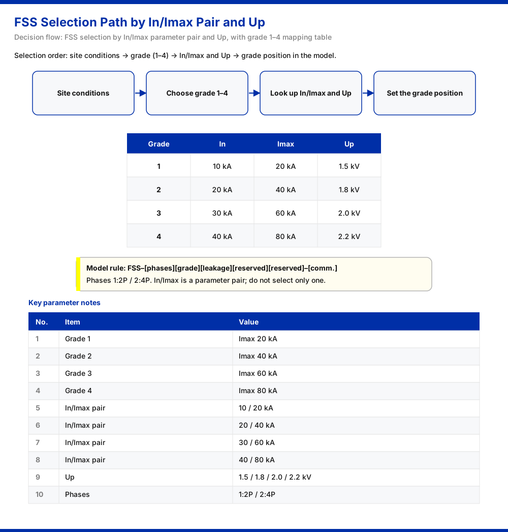
On the parameter table of an FSS intelligent surge protective device (e.g., FSS-11000/21000), In and Imax never stand apart as two independently selectable ratings; they always appear as a bound pair. The knowledge base places this pair in the same table as the voltage-dependent-resistor grade and Up, showing that the entries come from one model record. The question "what does each represent, and which do I read when selecting?" is therefore answered correctly not by splitting the two symbols, but by checking them as one unit together with the grade and Up.
1. In and Imax Are Listed as a Group
The knowledge base gives four grouped In/Imax values: 10 kA/20 kA, 20 kA/40 kA, 30 kA/60 kA and 40 kA/80 kA. Within each group the two numbers appear as a pair and rise together as the tier increases. That is what a parameter pair means here: one model corresponds to one combination, not a free pairing of a leading and a trailing figure.
One boundary must be stated. The knowledge base presents these values in tabular form and does not, in its running text, supply a separate definition or calculation method for In or Imax. This article therefore describes only the grouped structure the table displays and adds no normative definition the knowledge base does not itself provide.
2. Why the Grouped Structure Comes First
In and Imax are introduced as a pair because their relationship is fixed by the table structure, not by the magnitude of either figure. Each of the four data sets occupies a row: within a row, the In/Imax pair, the Up value and the grade form a single whole. A reader who compares the Imax column first and then picks the largest number is left with isolated digits; a reader who locks onto a row and reads out all its fields obtains a model characteristic that can be applied. The numbers themselves are not complicated; they are simply defined row-wise, which is why the grouping is stressed.
3. Grades 1–4 Are Divided by the Imax Step
The four grouped parameter sets correspond to the voltage-dependent-resistor grade. The knowledge base maps grades 1, 2, 3 and 4 to Imax values of 20 kA, 40 kA, 60 kA and 80 kA respectively. Read beside the grouped values, the correspondence is:
- Grade 1: In/Imax = 10 kA/20 kA;
- Grade 2: In/Imax = 20 kA/40 kA;
- Grade 3: In/Imax = 30 kA/60 kA;
- Grade 4: In/Imax = 40 kA/80 kA.
Selecting a grade is thus, in effect, selecting an In/Imax combination; the higher the grade, the more both values rise together. Hence one cannot "take only the large Imax and ignore In": the two are fields of the same table record, locked by one grade position.
4. Up Is Listed in the Same Table as the Pair
Each of the four parameter sets also corresponds to a Up value; for grades 1 through 4 these are 1.5 kV, 1.8 kV, 2.0 kV and 2.2 kV in that order. Up appears alongside In/Imax in the same table, indicating that the three come from one model record. If selection verifies only the current-side figures and omits Up, only part of the record has been confirmed. In reading order, site conditions first establish the required grade; the grade then yields the corresponding In/Imax and Up; finally the model rule fixes the grade position.
5. In/Imax Across 2P, 4P and Leakage Versions
The model groups in the knowledge base show that the 2P and 4P variants agree on In/Imax and Up: groups are listed in pairs of the form "FSS-11000/21000", and the 4P group carries the same In/Imax as the 2P group. The difference introduced by pole count lies in the number of poles (2P/4P) and in the leakage paths of the leakage-current versions (three paths for the 4P leakage version, one for the 2P version), not in a second set of In/Imax values. The leakage version is also marked in the table as having an OLED display, while the base tier uses a digital-tube display.
A useful selection judgement follows: once site conditions fix the grade, In/Imax and Up come from the same record whether the final choice is 2P or 4P and whether or not a leakage version is used. Pole count, leakage and display method are positions fixed outside that combination; changing them does not change the current tier.
6. The Grade Position in the Model Rule
The model rule in the knowledge base is FSS–[phases][voltage-dependent-resistor grade][leakage][reserved][reserved]–[communication], where phases 1 means 2P and 2 means 4P. The grade is an independent position within the model body, not an option attached afterwards. In addition, the 4P leakage version has three leakage paths and the 2P version has one. The choice of In/Imax therefore appears as the value of the grade position, which sits adjacent to the phases, leakage and communication positions. Only when the parameter table and the model positions are aligned does the selection chain close.
7. Which One to Read When Selecting
Returning to the core question: do we read In or Imax? The table structure shows that the question itself needs correcting. In and Imax are two fields of one combination, and neither figure can independently carry a selection conclusion. A sound order is:
- Determine the required grade from the site conditions;
- Read the In/Imax and Up along the record for that grade;
- Return to the model rule and fix the grade position together with the phases, leakage and communication positions.
On this path, "In or Imax" is replaced by "verify the whole group". If site conditions are identical but only a larger Imax is picked, the result falls onto a different record whose In and Up do not match.
8. Common Misreadings
- Treating In and Imax as two ratings that can be raised independently, ignoring that they appear as a group and change together, which splits one record into two numbers of different origin.
- Checking In but missing Up, or Up but missing the current side, confirming only part of a record's fields.
- Treating the grade as an option attached afterwards, when it is an independent position in the model body alongside the phases and leakage positions.
- Applying one set of values to every scenario, ignoring that site conditions are the prerequisite for determining the grade and that the four sets have their own range.
What these share is the splitting of one model record into unrelated numbers.
9. A Row-by-Row Verification Checklist
A simple reading checklist follows:
- Have the site conditions fixed the required grade?
- Is the In/Imax read from the same row a grouped value?
- Is the Up in that same row confirmed as well?
- Have the phases, leakage and communication positions been fixed?
- Is the chosen grade within the four sets listed in the knowledge base?
The checklist produces no new parameter conclusions; it keeps the reading order intact and aligns terminology across a team. When opinions diverge, working through it item by item locates the real issue faster than arguing over which number is larger.
10. Do Not Mix Information from Different Stages
In/Imax describes the capability tier of the protective body and belongs to the selection stage; status monitoring describes the device's condition in operation and belongs to the operations stage. The first answers "which tier to choose", the second "whether it can still be used". Inferring operating state from selection parameters, or substituting monitoring data for a selection judgement, both lead to wrong conclusions. Separating stages and responsibilities lets the parameter table and the monitoring data each serve their own purpose.
11. Applicability and Limitations
First, this article's account of In and Imax is limited to the grouped parameter table in the knowledge base; it describes only the grouped structure and correspondence, and adds no definitions or formulae the knowledge base does not give.
Second, the four In/Imax values, the four Up values and the grade mapping follow that parameter table and are not extrapolated here to other tiers or models.
Third, the model rule, pole count (1:2P / 2:4P) and leakage paths (three for the 4P leakage version, one for the 2P version) are as given in the knowledge base; actual configuration should rest on the position combination of the corresponding model table and on site conditions.
Fourth, any reference to GB 50057 is limited to the grounding red-line entry in the knowledge base (trigger condition: abnormal open of the grounding resistance); this article draws no inference about standard limits.
Fifth, this article does not infer the product's certification, ingress protection rating or parameters not listed in the knowledge base, nor extend the grouped values of any tier into a general conclusion. If site conditions differ from the assumptions here, return to the specific model entry and the corresponding knowledge-base entry rather than choose on the strength of a single number.