 FEXLINK Research Institute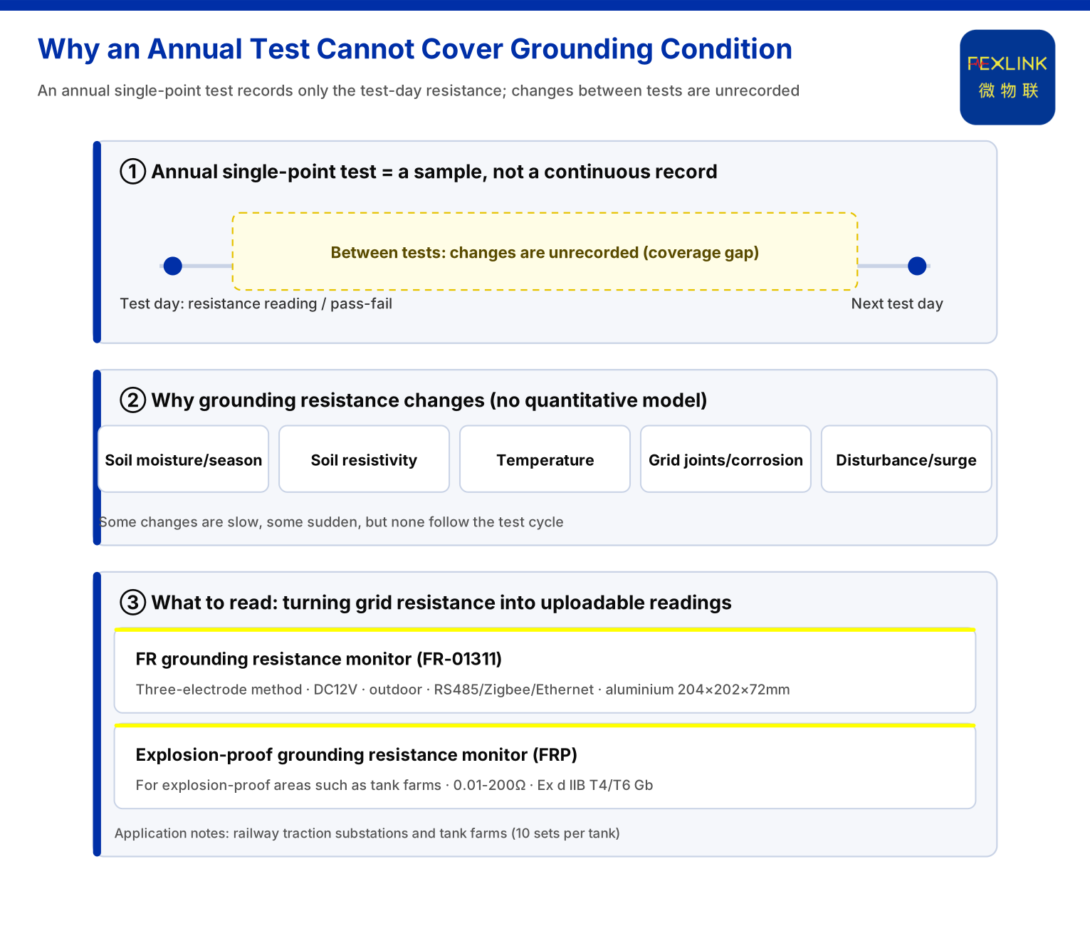
Grounding resistance is not a number fixed once it has been measured. A single annual test produces a "health-check snapshot": at the moment of testing, what the grid's resistance is and whether it passes. But lightning risk, soil condition and grid connections are not static, and what happens between two tests is not recorded in the snapshot. The knowledge base lists "abnormal open circuit of grounding resistance" as the non-bypassable red line, citing GB 50057 — which in itself says grounding is a line that must be held continuously, not merely "passing on test day." This article answers three questions: where the blind spots of annual testing lie, what online monitoring reads, and how it holds together at system level.
1. An Annual Test Gives a Snapshot, Not a Process
A test is essentially one sampling. It answers "what is the grounding resistance at the moment of sampling"; it does not answer "what happened to the grounding resistance between two samplings." If the test happens to be done in a dry season and the value passes, that report will not record how the grid changes when the wet season arrives; likewise, if the grid suddenly opens after an impulse or a construction disturbance, the report still says "pass" until the next test day.
This is not a problem with the test method but with the coverage of the cycle itself: any sampling at a fixed interval can describe only the sample points, not the process between them.
2. Why Grounding Resistance Changes, and When
Clarifying the blind spot still leaves a premise to answer: does grounding resistance change at all?
From engineering common sense, grounding resistance is affected by soil moisture and season, soil resistivity, temperature variation, and the condition of grid connections and corrosion; a construction excavation, or a single loosened or corroded connection, can move an otherwise passable grid away from its previous state. Some of these changes are slow, some sudden, but their common trait is that they do not follow the test cycle.
The knowledge base gives no quantitative model, correction factor or statistical law for how grounding resistance changes with season or environment. What the knowledge base does give is "abnormal open circuit of grounding resistance" as a non-bypassable safety red line — which at least indicates that grounding condition is treated in engineering as a quantity requiring continuous attention.
3. What Online Monitoring Reads: the FR Grounding Resistance Monitor
If one sampling a year cannot describe the process, grounding resistance must move from "a test-day value" to "a continuous reading." The product the knowledge base provides for this is the FR grounding resistance monitor (FR-01311). Under the model rule, the series is named by a "signal acquisition – measurement principle – installation – power – communication" combination: the principle is loop or three-point, the installation is outdoor or indoor, and the signal acquisition item is grid resistance.
The monitor uses three-point measurement, DC12V power and outdoor installation, with RS485, Zigbee and Ethernet communications; its enclosure is aluminium, 204×202×72 mm. The explosion-proof grounding resistance monitor (FRP) in the same series targets hazardous areas such as tank farms, with system-level reference parameters of 0.01-200 Ω and Ex d IIB T4/T6 Gb. For the question "can grounding condition be read continuously?", this is the carrier that takes grounding resistance out of the annual report and turns it into an uploadable reading.
The knowledge base also records that the FR/FRP series has been applied in railway traction-substation grid online monitoring and the Jinzhou Port tank farm (10 sets per tank); that application note is an internal record, and is cited here only as capability evidence.
4. From Measuring Points to Platform: Four-Layer Architecture, Protocols and System-Level Parameters
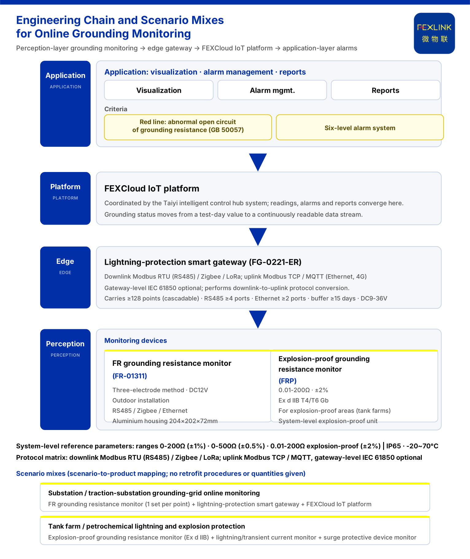
Reading is only the first step; data is meaningful only when it can travel upstream. The knowledge base defines the monitoring system as a four-layer architecture — perception, edge, platform, application: the perception layer collects from monitoring modules, smart meters and sensors, the edge layer gateway uploads to the FEXCloud IoT cloud platform, and the application layer presents visualisation, alarm management and analysis reports. The perception layer, where the grounding resistance monitor sits, is the entry to this architecture.
On the transport side, the knowledge base's communication protocol matrix is: device downlink supports Modbus RTU (RS485), Zigbee (Modbus) and LoRa; device uplink supports Modbus TCP/MQTT (Ethernet, 4G), with gateway-level optional IEC 61850. The FG lightning-protection intelligent gateway (for example FG-0221-ER) plays the role of downlink-to-uplink protocol conversion.
System-level reference parameters show grounding monitoring is a systematised engineering task: monitoring units cover 0-200 Ω (standard, ±1%), 0-500 Ω (high-precision, ±0.5%) and 0.01-200 Ω explosion-proof (±2%); protection rating IP65, operating temperature -20~70 °C; the intelligent gateway mounts ≥128 points (cascadable), with RS485 ≥4 ports and Ethernet ≥2 ports, data caching ≥15 days, and DC9-36V wide-voltage input. These parameters show that "online" is not an extra probe but a complete chain with range tiers, protection rating, mounting capacity and offline-cache design.
5. When to Adopt Online Monitoring
The knowledge base scenario table lists grounding-related needs as explicit combinations. For substation and traction-substation grid online monitoring the recommended combination is "grounding resistance monitor (1 set per point) + lightning-protection intelligent gateway + FEXCloud IoT cloud platform"; for tank-farm and petrochemical explosion-proof lightning protection it is "explosion-proof grounding resistance monitoring (Ex d IIB) + lightning/transient current monitor + surge protective device monitor".
Note: the knowledge base gives a "scenario-to-product" recommendation mapping.
6. Boundaries: What This Article Does Not Claim
Second, the knowledge base gives no test frequency for grounding resistance, no seasonal correction factor, no alarm threshold other than the "abnormal open circuit", and no retrofit procedure or quantity for online monitoring; this article asserts nothing about them.
Third, this article cites only the GB 50057 number listed in the knowledge base; it does not infer clause content or claim conformity with standards not listed. The FR/FRP application note in the knowledge base is an internal record, and is not a case or performance commitment.
Fourth, this article answers only "why grounding resistance cannot rely on a single annual test" and the online-monitoring capability it can draw on.
Conclusion
Grounding resistance cannot rely on a single annual test because one test is a sample point, not a process: it cannot cover the seasonal change, connection degradation and sudden open circuit between two tests. Closing that blind spot is not about testing more often but about turning grounding condition from "a test-day value" into "continuously readable data." What the knowledge base offers is concrete and verifiable: use the FR grounding resistance monitor and the explosion-proof grounding resistance monitor (FRP) to sense grid resistance, aggregate it via the lightning-protection intelligent gateway over the four-layer architecture and protocol matrix into the FEXCloud IoT cloud platform, and support engineering deployment with system-level range, protection and cache parameters; recommended combinations are given for substation/traction-substation grid online monitoring and tank-farm explosion-proof scenarios; and "abnormal open circuit of grounding resistance" as the red line signals that this line must be held continuously.