 微物联研究院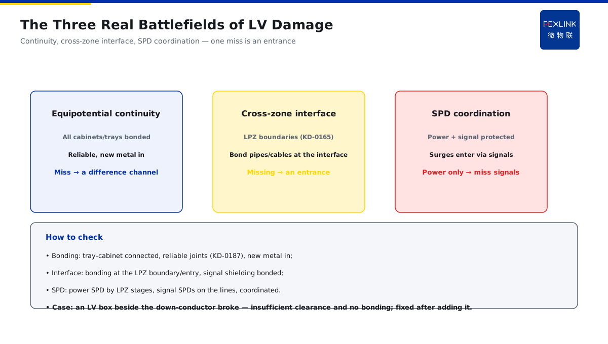
Direct Answer
The earthing resistance passes every year, so why does lightning still damage the low-voltage (LV) equipment? The answer: a passing steady-state earthing resistance only means good power-frequency dissipation — it does not mean the transient counterattack and equipotential bonding are sufficient. LV equipment damage usually comes from the potential difference caused by the earth-potential rise, missing equipotential bonding at zone boundaries, or no SPD on the signal/power paths. The diagnosis must expand from "the earthing resistance" to the equipotential continuity and the cross-zone SPD coordination, instead of only measuring the resistance.
At a park, the earthing resistance passed every year, but the LV equipment was still damaged by surges in the storm season. Measuring only the resistance could not explain it; after expanding the diagnosis, it was found that there was no equipotential bonding at the cabinet-tray zone boundary — when the earth potential rose during a strike, the potential difference between the two sides was large, and the surge entered through the signal lines. After adding cross-zone bonding and signal-line SPDs, there was no more damage. The key distinction: a passing resistance is not transient safety — the root causes of LV damage are mostly equipotential continuity and cross-zone coordination; the diagnosis must expand from the resistance to these two.
Why:
- The resistance dimension: a passing steady state only means good power-frequency dissipation;
- Equipotential bonding: is the continuity/cross-zone interface sufficient;
- SPD coordination: are the power and signal paths protected;
- The diagnosis: resistance → equipotential → SPD coordination.
Key insight: "A passing resistance is not transient safety — for LV damage, check the equipotential continuity and cross-zone SPD coordination; do not stare only at the resistance value."
At a plant, an LV box beside the down-conductor was damaged by a strike even though the resistance passed; the cause was insufficient clearance and no equipotential bonding with the down-conductor, so the current path counterattacked the LV equipment. Adding the equipotential connection fixed it. Lesson: a passing resistance is only the baseline — the potential difference from the earth-potential rise is the real enemy of LV equipment.
1. A Passing Steady-State Resistance Is Not Transient Safety
Step one: why it still breaks even when it passes.
Steady state vs transient:
- The steady-state resistance measures the power-frequency dissipation;
- The transient looks at the potential rise under the lightning current;
- The two are not the same;
- A passing resistance is not transient safety.
Why a potential difference appears:
- The earth potential rises the moment the lightning current enters the ground;
- The rise amplitude differs at different points;
- A potential difference forms between the devices;
- The difference drives a surge current into the equipment.
The misconception:
- "A passing resistance means safe";
- Measuring only the resistance, not the bonding;
- Cannot explain why the equipment broke;
- No direction for rectification.
Key insight: "A passing steady-state resistance only means good power-frequency dissipation — the potential difference from the earth-potential rise is the main cause of LV damage; do not treat a pass as an immunity certificate."
2. Is the Equipotential Continuity and the Cross-Zone Interface Complete
Step two: check the potential-difference channels.
Check the equipotential continuity:
- Are the cabinets/trays/shielding all bonded;
- Are the connection points reliable (connecting to KD-0187);
- Are new metal bodies brought in;
- The continuity decides whether the potential is one.
Check the cross-zone interfaces:
- The lightning-protection-zone (LPZ) boundaries (connecting to KD-0165);
- The entering/exiting pipes and cables across the zones;
- Is the bonding done at the interface;
- Missing bonding → the potential-difference entrance.
Common misses:
- The tray and the cabinet not connected;
- No bonding busbar at the cross-zone interface;
- Signal lines/shielding not bonded;
- New pipes not brought in.
Key insight: "Check the equipotential continuity and the cross-zone interface — all cabinets/trays bonded, bonding at the interfaces; one miss is a potential-difference entrance."
3. Are the Power and Signal Path SPDs in Place
Step three: check the surge entrances.
The power path:
- An SPD at the distribution entry (connecting to KD-0161);
- Protection of the LV equipment power;
- A missing power SPD → the surge enters through the power;
- Configure by LPZ stages.
The signal path:
- Signal/data/control lines;
- Matching signal SPDs;
- Surges often enter through the signal lines;
- The signal path is the easiest to ignore.
The coordination principle:
- Both the power and the signal need SPDs;
- Select by the path characteristics;
- The signal SPD coordinates with the power SPD;
- Focus protection on the interfaces.
Key insight: "Check the power and signal path SPDs — LV surges often enter through the signal lines; protecting both the power and the signal is complete protection."
4. Is the Earthing Grid Equalization Insufficient
Step four: check the grid itself.
The equalization role of the grid:
- The equalization net makes the potential rise consistent during a strike;
- The grid area/mesh affects the equalization;
- Insufficient equalization → a large local potential difference;
- A grid retrofit improves the equalization.
How to check:
- The grid mesh density;
- Local grids in the equipment areas;
- Whether independent earthing is merged (counterattack prevention);
- The equalization net connected to the main grid.
Common problems:
- Too large a grid mesh;
- No local equalization in the equipment areas;
- Independent earthing not merged;
- A large local potential difference on a strike.
Key insight: "Check the grid equalization — a dense mesh, local equalization, merged independent earthing; the potential rise is consistent and the difference is small."
5. The Diagnosis Order: Resistance → Equipotential → SPD Coordination
Step five: check in order.
The diagnosis order:
- ① The resistance: a pass is only the baseline (measured by the FR);
- ② Equipotential: continuity + cross-zone interface;
- ③ SPD coordination: the power + signal paths;
- ④ Grid equalization: mesh/local/merging;
- Check in order and record the data.
The treatments:
- A large difference → add bonding;
- A missing interface → do the cross-zone bonding;
- A missing path → add the power + signal SPDs;
- Poor equalization → denser mesh/local equalization.
Practice verification:
- Review after the retrofit in the storm season;
- The FR monitor + the FS SPD monitor;
- Event records closed;
- No more damage means it is good.
Key insight: "Diagnose in order: resistance (baseline) → equipotential (continuity/interface) → SPD coordination (power/signal) → grid equalization — treat the cause and verify by monitoring after the retrofit."
6. Product Implementation: Monitoring and Diagnosis as One
WeiWuLian products manage LV protection:
- FR Earth-Resistance Monitor: online resistance and earthing state;
- FS SPD Monitor: online SPD state/events;
- Equipotential check: continuity/interface data;
- Closed-loop diagnosis: resistance-bonding-SPD data.
The design principle in one sentence: "Resistance is the baseline, bonding is the main battlefield, SPD is the entrance — a three-dimensional data loop; LV protection no longer relies on guessing."
7. Common Misjudgments
- "A passing resistance means safe": ignoring the transient. Result: damage from the potential difference. Correct: expand the diagnosis to the bonding.
- "Measure only the resistance": ignoring the bonding. Result: no root cause found. Correct: resistance → bonding → SPD.
- "Only the power SPD": ignoring the signal path. Result: the surge enters through the signal lines. Correct: protect both.
- "No bonding across the zones": ignoring the interface. Result: a potential-difference entrance. Correct: bond the interface.
- "Independent earthing is fine": ignoring the equalization. Result: a large local difference. Correct: merge/local equalize.
Scope and Limitations
This article explains the diagnosis of the counter-intuitive "passing resistance but damaged LV equipment" failure (steady vs transient, equipotential continuity, cross-zone interfaces, power/signal SPD coordination, grid equalization and the diagnosis order), applicable to troubleshooting and understanding LV lightning damage. The exact parameters and requirements follow GB 50057-2010, GB 50343-2012 and the manufacturers' data; this article explains only the diagnostic logic and judgment basis. All cases are anonymized (a park, a plant) and do not refer to any specific customer.