 微物联研究院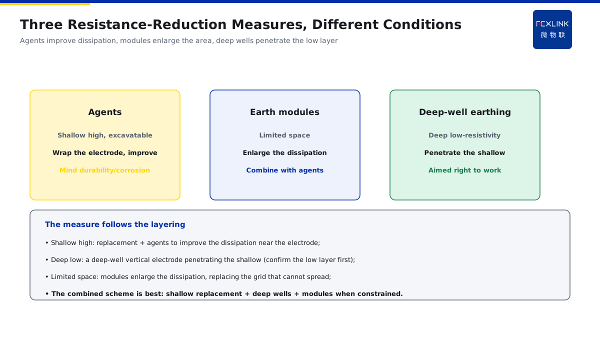
Direct Answer
When the earthing resistance in mountainous/sandy-stone areas cannot reach the standard no matter what, which resistance-reduction measure should be used? The answer: first judge whether the high resistivity is in the shallow or deep layer — for a high-resistivity shallow layer, replace the soil and use resistance-reduction agents to improve the dissipation near the electrode; when a low-resistivity layer exists in the deep layer, a deep-well vertical earth electrode is more effective; earth modules suit places with limited space where the dissipation area must be enlarged. The choice depends on the soil layering and the site — the more expensive deep well is not always better.
At a mountainous substation, the measured earthing resistance exceeded the limit; three deep wells were blindly drilled, costly and limited in effect — the wells still penetrated the high-resistivity rock. After a layered soil-resistivity test confirmed a high-resistivity sandy shallow layer and a low-resistivity groundwater deep layer, one deep well reaching the low-resistivity layer plus shallow replacement brought the resistance to standard at lower cost. The key distinction: resistance reduction is not "the more expensive, the better" — test the layering first and choose by "whether the high resistivity is shallow or deep"; a deep well drilled in the wrong place wastes the money.
Why:
- Layering first: measure the shallow/deep resistivity before deciding;
- Resistance-reduction agents: improve the dissipation near the electrode (shallow);
- Earth modules: enlarge the dissipation area (limited space);
- Deep-well earthing: reaches the deep low-resistivity layer (effective when deep).
Key insight: "Choose the measure by the soil layering: replacement/agents for the shallow, deep wells for the deep, modules when space is limited — test the layering before spending; a well in the wrong place wastes the money."
At a park, the site was too constrained to spread a horizontal grid and the resistance never reached the standard; earth modules enlarged the dissipation area and it passed. Lesson: the site constraint decides the measure — the deep well is not universal; when space is limited, modules plus agents are more practical.
1. Test the Soil-Resistivity Layering First
Step one: is the high resistivity shallow or deep?
Why layering matters:
- Shallow high resistivity → replacement/agents;
- Deep low resistivity → a deep well penetrating;
- Choosing the wrong measure wastes money;
- Layering is the starting point of selection.
The test method:
- The four-probe method measures the resistivity;
- Different spacings measure different depths;
- A resistivity-vs-depth curve;
- Identifying the shallow/deep high-low.
Reading points:
- Shallow high, deep low → a well is most effective;
- High everywhere → replacement + a larger dissipation surface;
- A local low layer → aim the well at it;
- The test guides the scheme, not guesswork.
Key insight: "Layer first, then reduce: the four-probe method gives the resistivity-vs-depth curve — see whether the high resistivity is shallow or deep, and the measure follows the layering."
2. Resistance-Reduction Agents: Improving the Dissipation Near the Electrode
Step two: what to do about a shallow high-resistivity layer.
The role of the agents:
- Wrapping the electrode and lowering the contact resistance;
- Improving the dissipation near the electrode;
- Enlarging the effective dissipation radius;
- The first choice for a shallow high-resistivity layer.
Applicable conditions:
- A shallow high-resistivity layer and the site allows excavation;
- Poor dissipation near the electrode;
- Combined with low-resistivity replacement;
- The amount follows the electrode geometry.
Notes:
- Choose long-lasting agents (prevent loss);
- Avoid corrosion of the electrode;
- Combine with the horizontal grid;
- Monitor the effect regularly.
Key insight: "Agents improve the dissipation near the electrode and enlarge the effective radius — first choice when the shallow layer is high-resistivity and excavatable; mind the durability and corrosion."
3. Earth Modules: Enlarging the Dissipation Area
Step three: what to do about limited space.
The role of the modules:
- Adding dissipation area in module form;
- Replacing a spread grid when space is limited;
- Combined with electrodes/grids;
- Efficient dissipation.
Applicable conditions:
- The site is too constrained to spread a horizontal grid;
- The dissipation area must be enlarged;
- Combined with agents/replacement;
- Flexible vertical/horizontal layout.
Notes:
- Reliable connections between modules;
- Conducting to the main grid;
- Burial depth matched to the environment;
- Monitor the resistance-reduction effect.
Key insight: "Modules enlarge the dissipation area when space is limited — when the grid cannot spread, use modules; combining with agents is more practical."
4. Deep-Well Earthing: Penetrating to the Deep Low-Resistivity Layer
Step four: what to do about a deep low-resistivity layer.
The role of the deep well:
- A vertical earth electrode penetrating the high-resistivity shallow layer;
- Reaching the deep low-resistivity layer/groundwater;
- Deep dissipation, a large drop in resistance;
- Most effective when the deep layer is low-resistivity.
Applicable conditions:
- A low-resistivity layer exists in the deep;
- The shallow layer cannot be fixed by replacement;
- The site allows vertical space;
- Effective only when aimed at the low layer.
Notes:
- Confirm the low-layer position by layering first;
- A well in the wrong place has limited effect;
- The depth/diameter match the geology;
- Connected to the shallow grid.
Key insight: "A deep well penetrates the high-resistivity shallow layer to the low-resistivity layer — but first confirm the low layer exists; a well in the wrong place wastes the money."
5. Weighing the Measure against the Site and Cost
Step five: how to set the scheme comprehensively.
The selection logic:
- Test the layering first;
- Shallow high → replacement/agents;
- Deep low → a deep well;
- Limited space → modules.
The cost trade-off:
- Deep wells are expensive and depend on the geology;
- Agents/replacement are cheaper and suit the shallow;
- Modules suit constrained sites;
- A combined scheme is the best.
Practice verification:
- Measure the resistance after construction;
- Monitor online with the FR Earth-Resistance Monitor;
- Recheck the seasonal variation;
- Add measures when it still fails.
Key insight: "Set the scheme by layering + site + cost: replacement/agents for the shallow, deep wells for the deep, modules when constrained — verify by measurement after construction."
6. Product Implementation: Resistance Reduction and Monitoring as One
WeiWuLian products manage the resistance-reduction system:
- FR Earth-Resistance Monitor: online monitoring of the earthing resistance;
- Layered testing: digitizing the soil resistivity;
- Effect recheck: verifying after resistance reduction;
- Data loop: reduction-monitoring-maintenance closed.
The design principle in one sentence: "Test the layering, choose by the layer, verify after construction, measure online — manage the reduction system with data."
7. Common Misjudgments
- "The more expensive the deep well, the better": ignoring the layering. Result: a well in the wrong place wastes money. Correct: test the layering first.
- "Use agents everywhere": ignoring the applicable conditions. Result: works shallow, fails deep. Correct: choose by the layer.
- "The deep well is universal": ignoring the site constraints. Result: cannot spread in a constrained site. Correct: combine modules.
- "Just do it without testing": ignoring the layering test. Result: the wrong measure. Correct: measure with the four-probe method first.
- "Done after construction": ignoring the effect verification. Result: a failure goes unnoticed. Correct: measure and monitor online.
Scope and Limitations
This article explains the resistance-reduction paths for high-soil-resistivity scenarios (layering first, and the applicable conditions and trade-offs of agents/earth modules/deep wells), applicable to selecting and understanding resistance-reduction schemes. The exact processes and parameters follow GB 50057-2010, related standards and the manufacturers' data; this article explains only the selection logic and judgment basis. All cases are anonymized (a mountainous substation, a park) and do not refer to any specific customer.