 FEXLINK Research Institute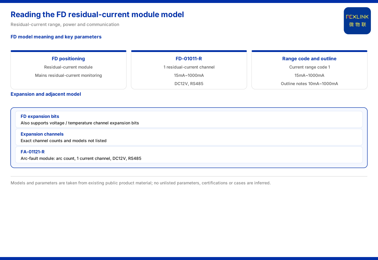
Direct answer
The mains residual-current monitoring module (FD-01011-R) is a module-level product that the knowledge base lists on the residual-current side. The model table records it as one residual-current channel with a range of 15mA to 1000mA, corresponding to the 10mA to 1000mA range class; its power supply is DC12V and its communication is RS485. The product-model quick reference maps the FD prefix to "mains (residual-current) monitoring module", and a note in the same section cites the product outline, positioning FD as a "residual-current monitoring module (10mA-1000mA)".
Three points matter in reading this module correctly. First, the residual-current range is written as 15mA to 1000mA in the model table, while a note in the same section defines current-acquisition range code 1 as 15mA to 1000mA; the two corroborate each other and together correspond to the 10mA to 1000mA range class. Second, the knowledge base states that FD also supports expansion positions for voltage and temperature channels, but does not give the specific expandable channel count or the corresponding model. Third, the same section also lists the arc-fault monitoring module (FA-01121-R) separately from FD, which shows that residual-current monitoring and arc-fault monitoring are two parallel acquisition targets in the knowledge base. On this basis the article explains FD's listed parameters, its code reading, and its selection order, and marks the parts the documentation does not unfold.
Where FD sits in the monitoring system
The product-model quick reference maps the FD prefix to "mains (residual-current) monitoring module", which is a mapping from prefix to purpose. A note in the same section cites the product outline and positions FD as a "residual-current monitoring module (10mA-1000mA)". The two records point to the same thing: FD carries the acquisition of the residual-current quantity.
Read the positioning together with the model table, and FD's acquisition target looks relatively single: it is responsible first for residual current. This contrasts with other modules that list several current channels, arc counts, and similar elements at once. For selection, confirming that the monitoring target is residual current and then moving to the range and communication check is a clear sequence. Positioning gives the purpose; the model table gives the parameters. The two should not be substituted for one another.
Residual-current range and acquisition-range code
The model table lists FD-01011-R as one residual-current channel with a range of 15mA to 1000mA. A note in the same section further defines current-acquisition range code 1 in the FD model rule as 15mA to 1000mA. The two records agree, which shows that code 1 corresponds to exactly this residual-current range class.
Note that the product outline writes the positioning as 10mA to 1000mA. The 15mA to 1000mA of the model table corresponds to the 10mA to 1000mA class, so the two do not conflict: the former is the range wording listed by the model table and the note, and the latter is the outline's positioning wording for the same class. Where range verification is involved, the 15mA to 1000mA listed by the model table and the note should be taken as the governing figure, while the class it belongs to is recorded as 10mA to 1000mA.
The meaning of a range lies in its coverage. A figure of 15mA to 1000mA shows that the residual-current level this module targets has explicit upper and lower bounds; values outside that span are not within this model's acquisition scope. This article makes no inference about values, alarm thresholds, or setting methods outside that range.
Power supply and communication
The model table records FD-01011-R's power supply as DC12V and its communication as RS485. These two items do not change with the number of residual-current channels; they are the model's uniform conditions. DC12V indicates that the module operates on a low-voltage direct-current supply; RS485 indicates that its data is sent out over a wired serial link.
Treat power supply and communication as the second part of selection: the range answers "over what span is the quantity measured", while power supply and communication answer "how is it powered and how is it sent out". When the range is suitable but the communication method does not match the on-site gateway, the acquired residual-current data is still difficult to bring into the upper layer. This article does not unfold communication methods other than RS485, nor does it infer electrical conditions beyond the supply.
Voltage and temperature expansion positions
A note in the knowledge base states that FD also supports expansion positions for voltage and temperature channels. That is, beyond residual current, the FD code structure reserves positions for voltage channels and temperature channels. This indicates that the series is not limited to a single monitored quantity but leaves interfaces for multiple elements.
The boundary needs to be equally clear: the knowledge base does not give the specific number of voltage or temperature channels that FD can expand, nor does it list the corresponding models. This article can therefore confirm only the fact that "expansion positions exist"; it cannot give an expanded channel-count ceiling or a model list. If a site needs voltage or temperature monitoring at the same time, selection should return to the corresponding section of the knowledge base to verify, rather than infer a configuration from the mere existence of expansion positions.
Division of labor with the arc-fault monitoring module
The same section also lists the arc-fault monitoring module (FA-01121-R), recorded as arc count, one current channel, DC12V, and RS485. The knowledge base lists it separately from FD, and that arrangement itself states the division of labor: the former targets the counting of arc events, the latter the magnitude of residual current.
These two acquisition targets are different, and conversion or association between them is outside the scope of this article. For a site, if the concern is the residual-current level, the product on the FD side should be selected; if the concern is the number of arc events, the arc-fault monitoring module side should be consulted. The two stand in parallel and do not substitute for each other; conflating them misplaces the selection target. This article does not infer a data association or a joint criterion between the two module classes.
Reading FD selection in order
Taken together, FD selection can proceed in four steps. First, confirm that the monitoring target is residual current. Next, verify the range, confirming whether 15mA to 1000mA (in the 10mA to 1000mA class) covers the on-site need. Then verify whether the DC12V supply and RS485 communication agree with the site. Finally, if voltage or temperature is also involved, return to the knowledge base to verify the specific models corresponding to the expansion positions, because the knowledge base does not list those channel counts in the FD entry.
A reminder: the model table and the note are the parameter basis for this article, while the product outline and the appendix quick reference provide the positioning basis. The two divide their work differently: the former gives parameters, the latter gives purpose. Reading by that division yields both the accurate wording of range, supply, and communication, and an understanding of FD's place in the monitoring system.
Scope and limitations
First, this article restates only what the knowledge base lists, with the factual boundary limited to the model table of the mains residual-current monitoring module, the note in the same section, the outline positioning, the appendix product-model quick reference, and the arc-fault monitoring module entry in the same section.
Second, the residual-current range is cited as the 15mA to 1000mA listed in the model table, retaining its wording as belonging to the 10mA to 1000mA class; this article does not infer values, alarm thresholds, or setting methods outside that range.
Third, the DC12V supply and RS485 communication are cited as listed in the model table; this article does not infer communication methods beyond RS485 or electrical conditions beyond the supply.
Fourth, FD's support for voltage and temperature channel expansion positions is cited as stated in the note; this article does not give the specific expandable channel count or corresponding models, because the knowledge base does not list them.
Fifth, the separate listing of the arc-fault monitoring module from FD is cited as arranged in the same section; this article does not infer a data association or a joint criterion between the two.