 FEXLINK Research Institute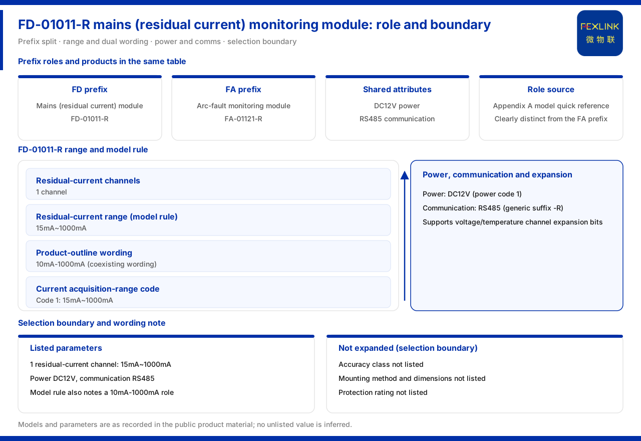
Direct answer
The mains residual-current monitoring module (FD-01011-R) measures residual current, and two ways of writing its range appear in the public entry. The product knowledge base positions it in the entry as one channel of residual current at 15 mA to 1000 mA and notes that this corresponds to the 10 mA to 1000 mA grade; a note below the table also records that the product outline positions the product as a residual-current monitoring module at 10 mA to 1000 mA. In other words, 15 mA is the model-rule definition and 10 mA is the product-outline definition.
The two definitions coexisting does not mean they contradict each other; they are two records retained side by side in the material. Beyond that, the entry also gives a supply of DC 12 V, communication of RS485, and a channel count of one. This article sets out the range definitions, the model rules, the side-by-side relationship with the other product in the same table, and the specification items the material has not yet listed.
1. Two ways the residual-current range is written
The product knowledge base gives two ways of writing the residual current range of the mains residual-current monitoring module (FD-01011-R). One is the model-rule definition, recorded as 15 mA to 1000 mA; the other is the product-outline definition, recorded as 10 mA to 1000 mA.
What the two ways share is the same upper limit of 1000 mA; the difference is at the starting end, one recorded as 15 mA and the other as 10 mA. Understanding this difference prevents treating one of the definitions as the only correct value during selection or acceptance. The prudent approach is to treat both as records in the material and to confirm, according to the actual use scenario, which definition governs the starting end.
2. The current acquisition range code in the model rules
The note below the table of the product knowledge base states that, in the model rules of this module, a current acquisition range code of 1 corresponds to 15 mA to 1000 mA. The note also records that the model rules support extension positions for voltage and temperature channels.
This shows the model of the module expresses more than the current range alone. The current acquisition range is a coded field, while voltage and temperature channels retain extension positions. For cases that need to cover voltage or temperature alongside residual current, these extension positions offer room for combination; how the combination actually works depends on the actual extension-position values, which the product knowledge base does not develop one by one in the entry.
3. Channels, power supply and communication
The entry describes the module as one channel of residual-current monitoring. The supply is DC 12 V and the communication is RS485. Together with the range, these form the full set of main parameters the entry gives.
Supply and communication can also be corroborated in the general rules. The general suffix of the product knowledge base defines R as RS485, carrying Modbus, and the supply code defines 1 as DC 12 V, matching the RS485 and DC 12 V marked on the module. From naming to parameters, therefore, the communication and supply of the mains residual-current monitoring module can be explained self-consistently, with no inference that needs external supplementation.
4. Side-by-side placement with the arc-fault monitoring module
In the same table, the mains residual-current monitoring module (FD-01011-R) sits beside the arc-fault monitoring module (FA-01121-R). The latter collects arc count on one current channel, with a DC 12 V supply and RS485 communication, matching the former in supply and communication.
The two sit side by side yet have different positions: one measures residual current, the other measures arc count. The model quick reference of the product knowledge base also labels the FD prefix as the mains residual-current monitoring module and the FA prefix as the arc-fault monitoring module, separating the two at the naming level. At selection time, the module should be entered according to the physical quantity being measured, and one must not be substituted for the other simply because the supply and communication are the same.
5. The place of module-level products in the monitoring system
The mains residual-current monitoring module belongs to module-level monitoring products. The arc-fault monitoring module at the same level is likewise of this kind; what they share is a compact structure and a focus on a single channel or single physical quantity, which makes them easy to fit inside existing distribution or utilisation equipment.
The significance of module-level products is that they push monitoring capability down into the equipment rather than adding a separate device. The residual-current monitoring module gathers leakage current in a circuit and provides a source of quantities for judgement at higher levels. Understanding this level placement helps distinguish it from controllers that carry a display and multi-channel expansion.
From the interface path, a module-level product still has to connect to higher levels. This module communicates over RS485 in the Modbus manner, which shows its data is to be gathered through a bus into a gateway or platform. The DC 12 V supply and RS485 communication are the two basic conditions for connecting it to a system. If a site already has DC supply and an RS485 bus, the module has met its connection conditions; if not, the power take-off and communication link must be resolved before parameter matching is discussed.
6. Specification items the material does not list
In the entry and the model quick reference, the product knowledge base gives only the channel count, range, supply and communication of the module; it does not list its accuracy class, mounting method, external dimensions or protection rating. These items often bear directly on field installation and acceptance but are currently unlisted.
When a specific integration is involved, therefore, accuracy, mounting method, dimensions and protection rating should be put on a to-confirm list and the corresponding material requested from the supplier, rather than inferred from the existing entry. What can be confirmed is one channel of residual current, the two range definitions, the DC 12 V supply and the RS485 communication; what cannot be confirmed is the four items above. Holding this boundary prevents an engineering conclusion from being drawn on incomplete material.
7. How to move selection and integration forward
Taken together, existing information allows progress on the following points. First, confirm that the measured object is residual current and choose the mains residual-current monitoring module rather than the arc-fault monitoring module. Second, record that the range has two definitions, 15 mA to 1000 mA and 10 mA to 1000 mA, with the starting end governed by the definition actually confirmed. Third, prepare the supply as DC 12 V and the communication as RS485. Fourth, if voltage or temperature is needed, separately confirm the combination through the extension positions in the model rules. Fifth, accuracy, mounting method, dimensions and protection rating must be requested separately.
Moving forward on these points separates the usable information from the to-confirm information within the material boundary. The product knowledge base can answer what the module measures, how the range is written, and how it is powered and communicates; it cannot answer its accuracy, mounting and protection specifications. This both makes full use of the material and stays within its boundary.
Scope and limitations
First, this article restates only what the product knowledge base lists; the factual boundary is limited to the mains residual-current monitoring module entry, its note below the table, the model quick reference, and the general suffix and supply code.
Second, the two ways of writing the residual-current range of the module are cited as listed in the product knowledge base; this article does not rule that one of them is the only correct definition.
Third, the channel count, supply and communication of the module are cited as listed in the product knowledge base; this article does not infer its accuracy class, mounting method, external dimensions or protection rating.
Fourth, the position and parameters of the arc-fault monitoring module are cited as listed in the product knowledge base; this article does not conflate it with the residual-current monitoring module.
Fifth, the voltage and temperature extension positions in the model rules are cited as listed in the product knowledge base; this article does not infer their specific combination values.