Offshore Wind Farm Smart Lightning Protection Monitoring
Using FS Lightning Current Monitoring Monitor, FL Transient Current Monitor, FR Three-Point Method Grounding Resistance Monitoring Module & FG Smart Gateway, to Offshore Wind Farm Tower SPD, Lightning Current, Grounding Resistance to 7×24 Hours Online Monitoring, Real-Time Sense Lightning Events & Lightning Protection System Status, Ensure Offshore Wind Farm In Lightning-Prone Sea Areas of Safety Stable Operation.
01 · BACKGROUND
Customer Background
Enterprise Type
An Offshore Wind Power Operator,Specializing in Offshore Wind Farm Development、Construction&Operation,isNational New Energy Key Development Area,Equal Emphasis on Safe Operation & Power Generation Efficiency.
Enterprise Scale: Hazard warning
Wind FarmScale
Offshore Wind Farm Contains Dozens of Wind Turbines, Tower Height Large, Blade Height Centralized, in Lightning-Prone Sea Areas, Lightning Risk Significantly Higher than Onshore.
Installed CapacityCapacity/Unit Count:Online inspection
Industry Position
National New Energy Infrastructure, Need Strict Compliance with GB/T 31456 "Wind Turbines Lightning Protection" & NB/T 31004 "Offshore Wind Farm Lightning Protection Design Specifications" & Other Industry Standards.
Compliance Standard: GB/T 31456 / NB/T 31004
02 · CHALLENGES
Business Challenges
Lightning-Prone Sea Areas, Lightning Event Frequent
Offshore Wind Farm Tower Height Can Over 100 Meters Up, in Lightning-Prone Sea Areas, Annual Lightning Strike Days Significantly Higher than Onshore, Tower & Blade Frequent Withstand Direct Lightning & Induced Lightning Strike.
Offshore Inspection Cost High, Window Short
Offshore Wind Farm Tower Inspection Requires Boat Trip, Affected by Sea Conditions, Weather, Tides Affect Significantly, Inspection Window Short, Single-Trip Cost High, Hard to Achieve High-Frequency Full-Cover Inspection.
SPD Degradation & Grounding Resistance Change Hard to Sense
Tower Top SPD Long-Term Lightning Strike Shock Exists Degradation Risk, Marine Salt Spray Environment Accelerates Grounding Grid Corrosion Causes Grounding Resistance Change, Lack Online Monitoring Means Cannot Early Warning.
Lightning Strike Fault Locate & Classification Lack Data
Lightning Causes Unit Fault Downtime After, O&M Team Hard to & Time Locate Lightning-Struck Units & Assessment Lightning Level, Affect Fault Handling Efficiency & Insurance Claim Evidence.
03 · SOLUTION
Solution
System Architecture Diagram

Note: This is a technical illustration. Architecture: sensing layer (FS/FL/FR terminals) → edge & network layer (FG Lightning Protection Gateway) → platform layer (FEXCloud IoT Cloud Platform).
Deployed Product List
| Product Name | Model | Quantity | Function |
|---|---|---|---|
| FS Lightning Current Monitoring Monitor | FS | Configured per point | Deployed atTower Top,Real-Time Monitoring of Lightning Current Amplitude、Polarity、Wavetom,Record Lightning Event & Tiered Alarm |
| FL Transient Current Monitor | FL | Configured per point | Deployed at Tower Power Circuit, Monitor SPD Surge Discharge Current, Assessment of SPD Operation Count & Remaining Life |
| FR Three-Point Method Grounding Resistance Monitoring Module | FR | Configured per point | Online Measurement Tower Grounding Grid Grounding Resistance, Resolution 0.01Ω, Real-Time Sensing Marine Salt Spray Corrosion Causes of Grounding Degradation |
| FG Smart Gateway | FG | Configured per point | Deployed atTower-BaseControl Cabinet,AggregationFS/FL/FRand other terminalsData,ThroughOptical Fiber/4GUploadCloud Platform |
| FEXLINK Cloud Platform | Cloud 3.0 | 1 Set | Data Aggregation、Visualization Display, Lightning Event Alarm、Compliance Report Auto Generation、Insurance Claim EvidenceSupport |
Note: Product quantities follow the point-based configuration principle; final quantities are subject to site survey and the implementation plan.
Network Topology
Sensing Layer: FS Lightning Current Monitoring Monitor Deployed at Tower Top Lightning Rod Downlead Point, FL Transient Current Monitor Deployed at Tower Power Circuit SPD Downstream, FR Three-Point Method Grounding Resistance Monitoring Module Deployed at Tower-Base Grounding Downlead Point, Cover Lightning Monitoring, SPD Monitoring, Grounding Monitoring Three Major Dimensions.
Network Layer: Each sensing terminal connects via RS485 bus (Modbus-RTU Protocol) Access Tower-Base FG Smart Gateway, FG Gateway uploads via Submarine Optical Cable/4G Cellular Network Uplink to Onshore Control Center Grid Network, Key Links Support Redundant Backup, Ensure Offshore Communication Reliability.
Platform Layer: Data aggregates to FEXLINK Cloud Platform (Private Deployed at Onshore Control Center), Provide Web & Mobile Visualization Dashboard, Lightning Event Real-Time Alarm, Historical Lightning Database, Compliance Report Auto Generation, Multi-Role Permission Management & Other Functions.
Integration Layer: Cloud Platform Through Standard REST API / Modbus TCP Protocol, & Wind Farm SCADA, CMS Status Monitoring System, Insurance Claims System Integration, Achieve Lightning Event Linked Alarm, Unit Fault Correlation Analysis & Claim Evidence Data Sharing.
04 · IMPLEMENTATION
Implementation Process
Site Survey & Solution Design
Engineers Visit Onshore Control Center & Offshore Tower Site, Survey Tower Lightning Protection Structure, Grounding Grid Layout, SPD Installation Location,outputting point list and system deployment plan.
Timeline: per project schedule
Equipment Installation & Wiring
Leveraging Offshore O&M Vessel Window, FS/FL/FR Installed in Batches to Tower Each Point, FG Smart Gateway Centralized Deployment at Tower-Base Control Cabinet, Complete RS485 Wiring & Power Connection.
Timeline: per project schedule
System Commissioning & Platform Integration
Configure FG Gateway Acquiring Parameters & Upload Transmission Cycle, Complete FEXLINK Cloud Platform Account Setup, Point Binding, Lightning Strike Alarm Threshold Setting, & SCADA System Integration Commissioning.
Timeline: per project schedule
Trial Operation & Personnel Training
System Trial Operation& Calibration Data Accuracy,toO&MPersonnel to Platform Operation、Lightning Alarm Handling、Report Export、Claim Evidence& Other Training,CompleteProject Acceptance & Delivery.
Timeline: per project schedule
05 · RESULTS
Application Effects
7×24h
All-Weather Online Monitoring
subject to site survey
MonitoringUnit CoverSeveral
subject to site survey
Reduction of Offshore Inspection Count
subject to site survey
Lightning EventRecord Count
subject to site survey
SPDDegradation Early Warning Count
Auto
Lightning Event Can Traceability Rate
Application Value
"subject to site survey Application Value to This CaseTo be Added After Customer Confirmation,TestimonialContent Will CoverSystem DeploymentBetoe & AfterOffshore Inspection Efficiency MoM、Lightning Event HandlingCases、Insurance Claim Evidence Improvement& OtherDimensions."
— Qualitative statement based on solution design objectives
06 · RELATED PRODUCTS
Related Product Recommendations
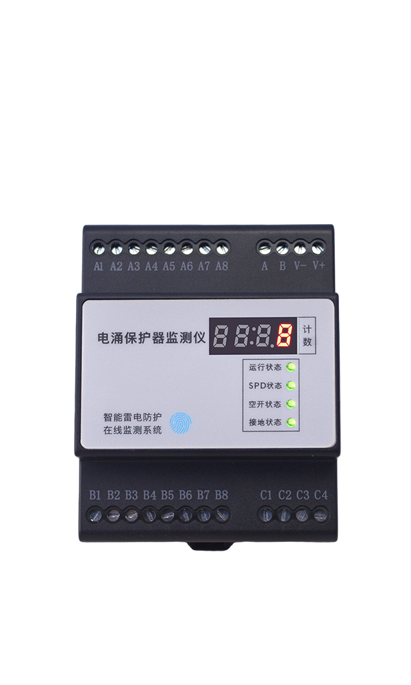
Smart Lightning Protection
FS Lightning Current Monitoring Monitor
Lightning CurrentAmplitude · Polarity · WavetomRecord
View Product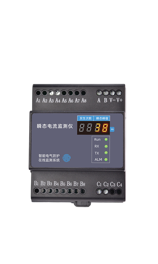
Smart Lightning Protection
FL Transient Current Monitor
SPDSurge Discharge Current · LifeAssessment
View Product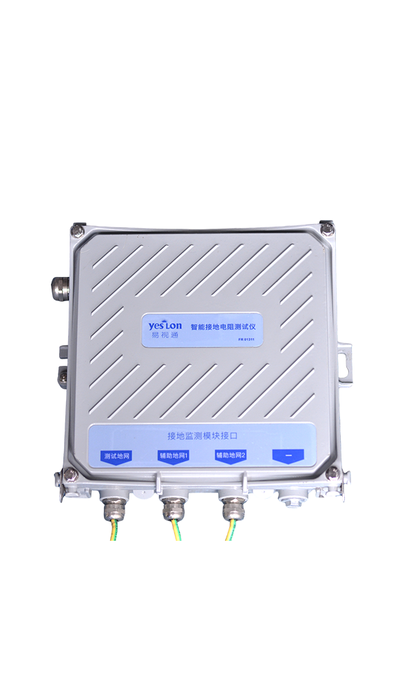
Smart Lightning Protection
FR Three-Point Method Grounding Resistance Monitoring Module
0.01Ω Resolution · Three-Pole Method · Online Monitoring
View Product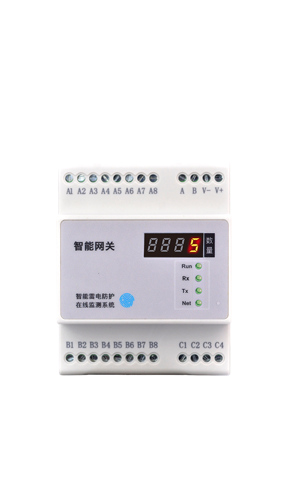
Smart Lightning Protection
FG Smart Gateway
Multi-Protocol Aggregation · Edge Computing · Optical Fiber/4GUplink
View Product07 · RELATED CASES
Related Cases
Beijing Winter Olympics the Venue Lightning Safety Monitoring
StadiumLightning Safety Monitoring,Ensure During EventsElectrical& Lightning Protection SystemStable Operation.
View DetailsA Major Grid Operator Smart Monitoring
Grid Substation & Distribution Facilities Smart Monitoring,Improvement of Grid Operation Reliability.
View DetailsA Cross-Sea CorridorElectrical Safety Monitoring
Cross-Sea Bridge-Tunnel Corridor Distribution System & Tunnel M&E Facilities Electrical Safety Online Monitoring.
View DetailsGet Similar Solution
If your enterprise has For SimilarOffshore/Onshore Wind FarmLightning ProtectionMonitoring Needs, Please Contact Us to a customized solution. The FEXLINK technical team will provide solutions based on your Wind FarmScale、Unit Count、Sea AreaLightning Characteristics,providing end-to-end IoT solutions.
FEXLINK Business Scope
FEXLINK 微物联,专注配电场景电气安全与数字能源技术研发。我们以多维精准感知与智能算法为核心,通过端侧感知芯片、多维电气时序特征算法、三层电碳大模型,实现雷电防护、接地监测、电气隐患识别;同步完成配电计量、电能质量分析、回路级碳排核算。面向老旧柜体与工业配电,构建从现场采集、本地芯片推理到云端电碳智能中枢的端云协同体系,赋能能源安全管控、能效优化与低碳数字化落地。