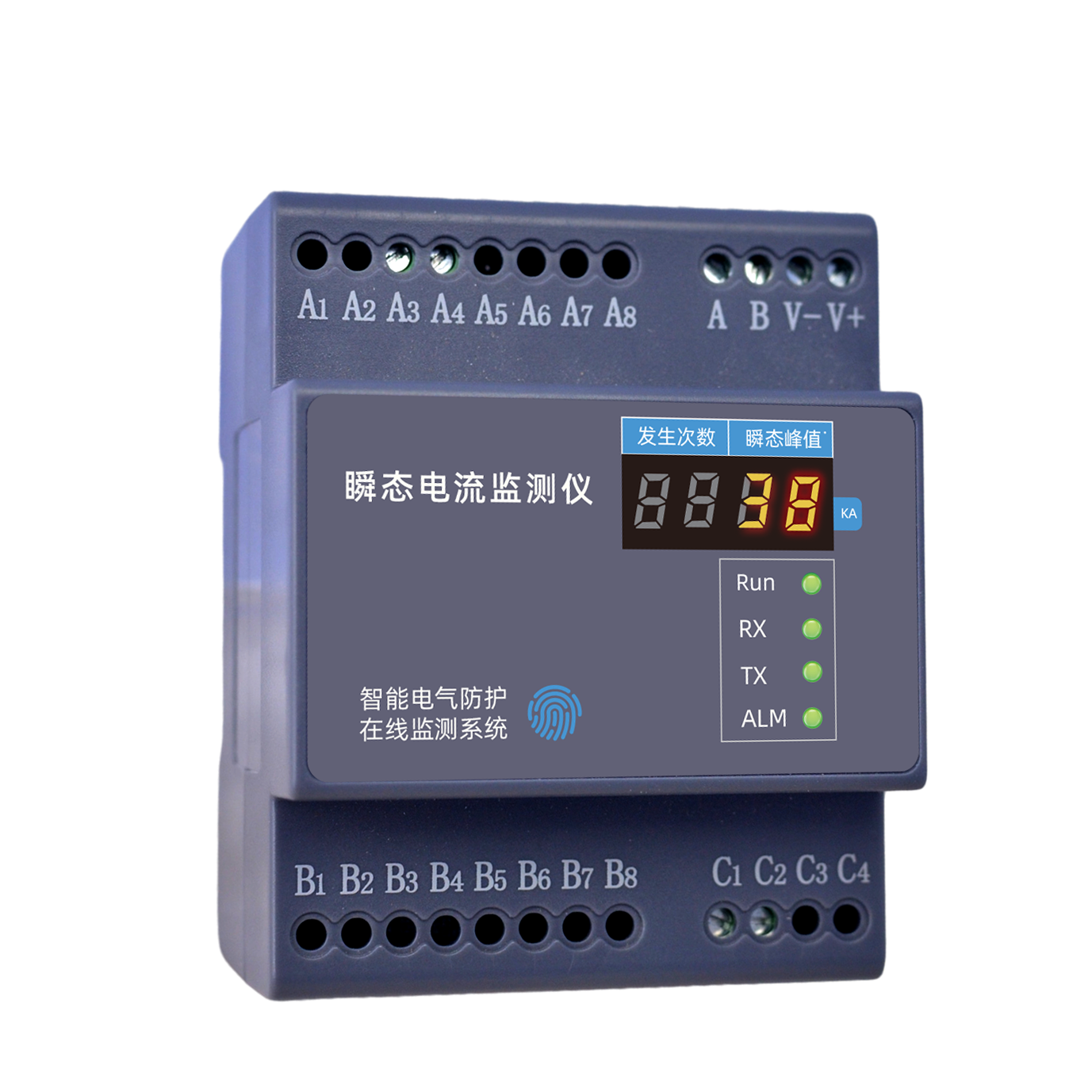
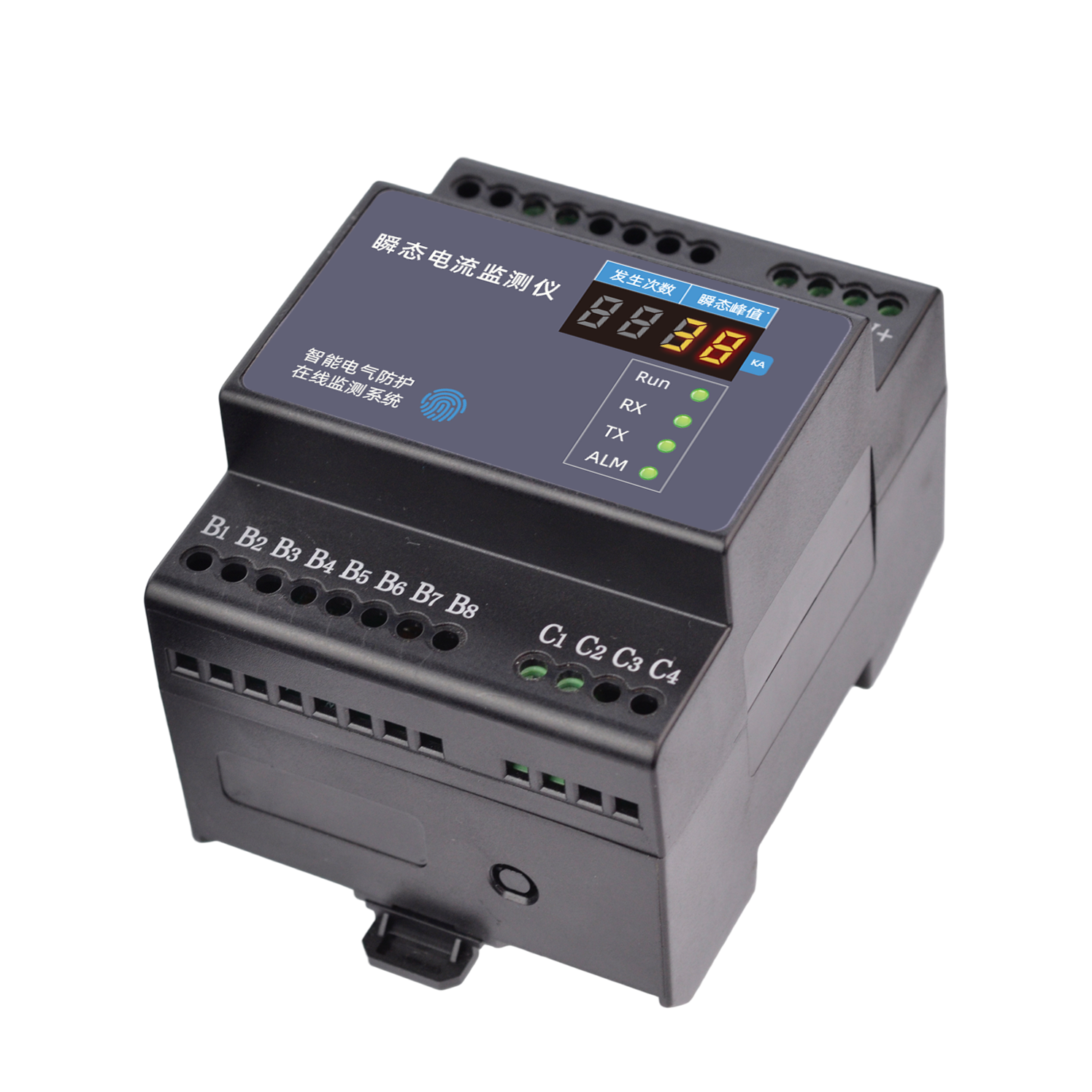
FL Transient Current Monitor - lightning current monitoring
Real-Time recording and analysis of lightning current and transient current events with peak value, waveform and charge transfer capture
The FL Transient Current Monitor provides Real-Time recording and analysis of lightning current and transient current events. It captures peak value, waveform and charge transfer data, enabling comprehensive lightning protection assessment and post-event analysis for distribution rooms and critical infrastructure.
Product Overview
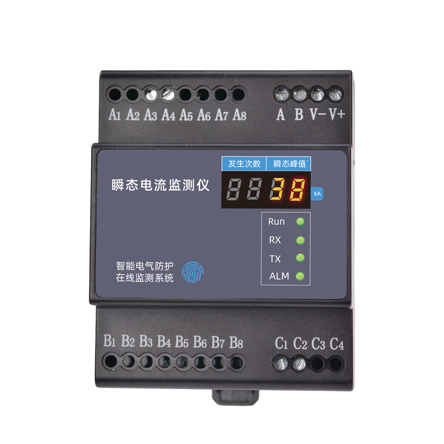
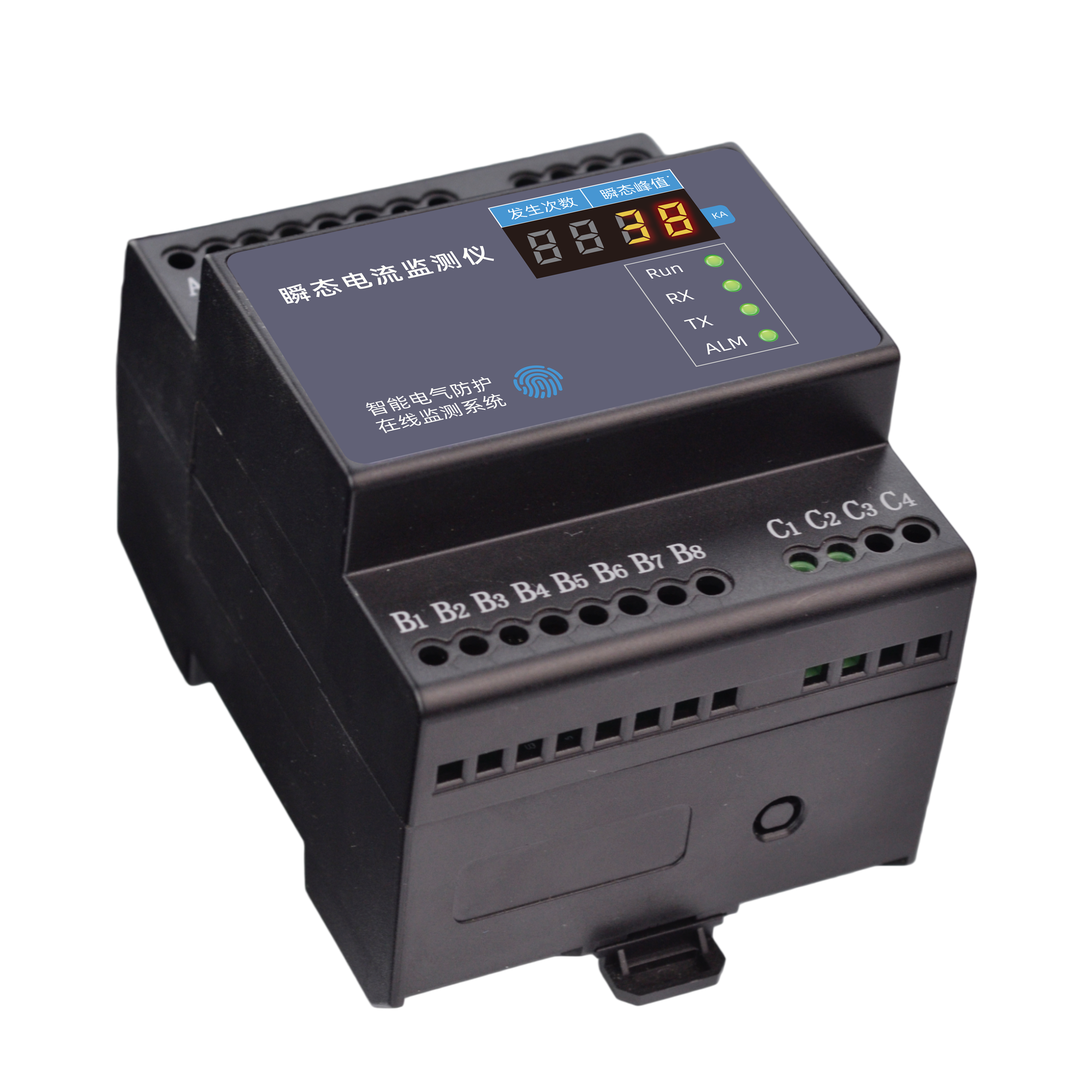
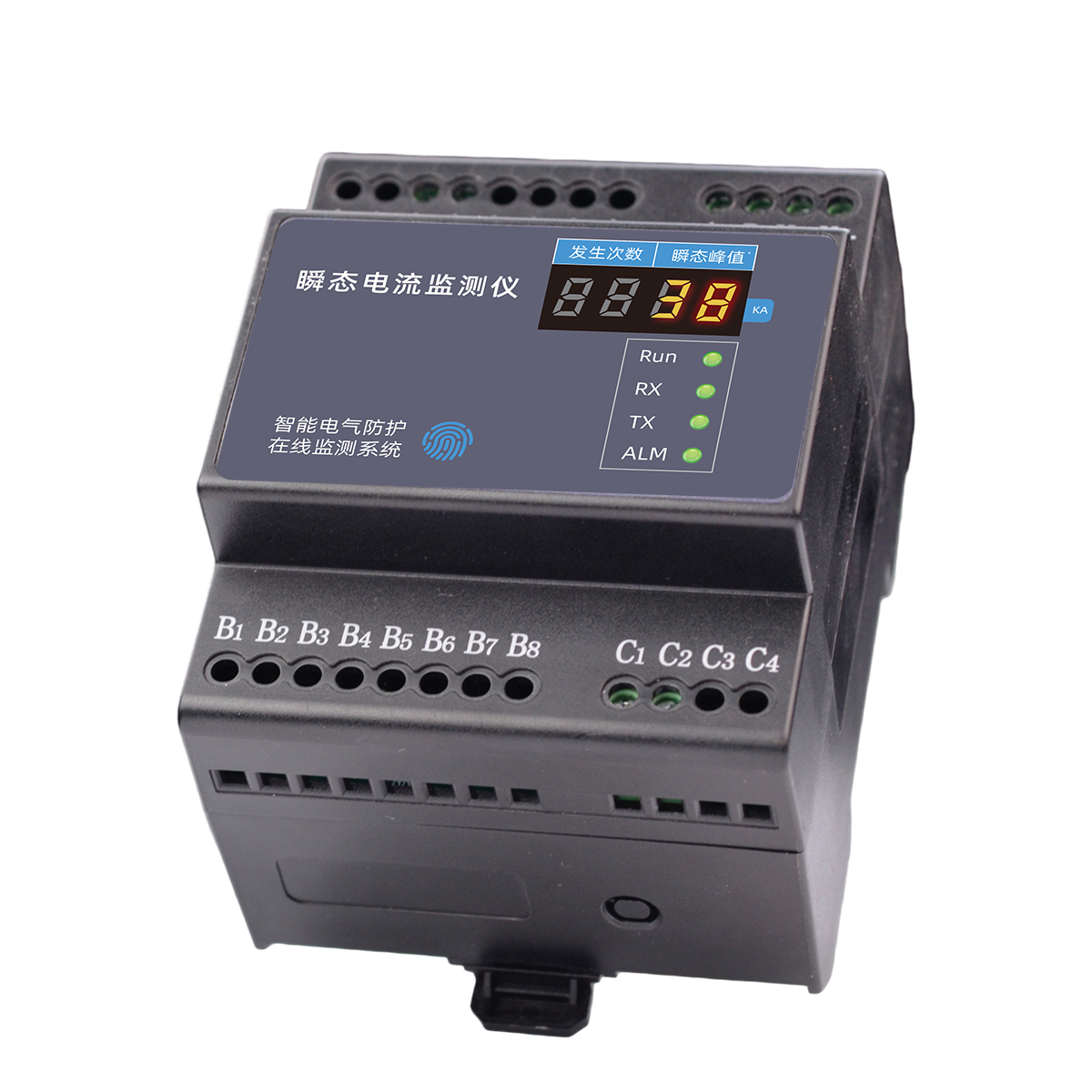
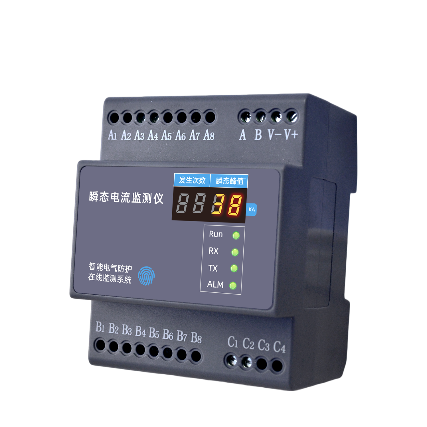
The FL Transient Current Monitor integrates "measure, control, transmit, and intelligize" in one unit, with fast response, fast computation, multiple counts, multiple types, and high acquisition accuracy. Uses high-precision Rogowski coil and digital integrator algorithm to ensure high-speed and accurate data.
Widely used in equipment lifecycle management, arc fault/arcing monitoring, external overvoltage monitoring, electrical safety hazard monitoring in high/low voltage distribution cabinets, predictive maintenance of load motors, suitable for military, petrochemical, construction, railway, port, airport, new energy and other fields.
Core Capabilities
- Fast response: 1S (microsecond) instantaneous acquisition; Fast computation: 1mS (millisecond) to complete calculation.
- 1S cycle can complete 60+ overvoltage monitoring, supports multiple overvoltage waveform acquisition.
- Acquisition accuracy up to ±3%, acquisition range customizable: 0.1KA-10KA, 1KA-100KA.
- Zero flux, high shielding, simulation-designed dedicated one-to-one high-agility Rogowski coil.
Product Features
Fast
Fast response: 1S (microsecond) instantaneous acquisition (1/1000000 second); Fast computation: 1mS (millisecond) to complete calculation (1/1000 second).
Multiple
Multiple counts: 1S cycle can complete 60+ overvoltage monitoring; Multiple types: supports multiple overvoltage waveform acquisition.
High Standard
High acquisition accuracy: up to ±3%; Customizable range: 0.1KA-10KA, 1KA-100KA; Comprehensive types: multi-group, multi-type waveform peak detection.
High-Precision Rogowski Coil
High-precision Rogowski coil and digital integrator algorithm, using zero flux, high shielding, simulation-designed dedicated one-to-one high-agility Rogowski coil, combined with digital integrator, ensures high-speed and accurate data.
All-Climate Sensor
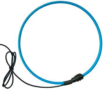
Split-core flexible Rogowski coil operates stably under strong electromagnetic interference, adapting to complex industrial field environments.
Wide Applications
Equipment lifecycle management, arc fault/arcing monitoring, external overvoltage monitoring, electrical safety hazard monitoring in high/low voltage distribution cabinets, predictive maintenance of load motors.
Selection Guide
Model Naming Rules
| Model | Mounting Environment | Function | RS485 | Zigbee | Ethernet | MQTT |
|---|---|---|---|---|---|---|
| FL-11122-R | Indoor | Peak | Yes | --- | --- | --- |
| FL-11122-Z | Indoor | Peak | --- | Yes | --- | --- |
| FL-11122-E | Indoor | Peak | --- | --- | Yes | Yes |
Technical Specifications
Basic Parameters (Indoor)
| Operating Voltage | AC 220V±20% |
| Power Consumption | 2W |
| Operating Temperature | -20℃~60℃ |
| Operating Humidity | <95% |
| Product Weight | 160g |
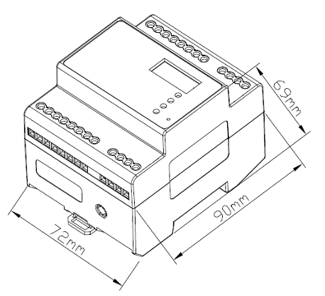
| Dimensions | 72*90*69mm (L*W*H) |
| Housing Material | Thermoplastic UL94V0 |
| Protection Class | IP20 |
| Mounting Method | Standard 35mm DIN rail mounting |
Smart Monitoring Functions
| Communication Method | RS485/Zigbee/Ethernet |
| Communication Protocol | Modbus protocol/MQTT protocol |
| Transient Current | High-frequency pulse, multi-wave features |
| Acquisition Range | 50A~5kA(customizable) |
| Acquisition Accuracy | ±3% |
| Data Storage | 100 records, auto-overwrite |
| Polarity | Positive/Negative |
| Occurrence Time | YYYY.MM.DD.HH.MM.SS |
Installation Instructions
Installation dimensions
Sensor Description
Sensor Specifications
| Sensor Type | Rogowski coil |
| Design Features | Zero flux, high shielding, simulation design |
| Structure | Split-core flexible Rogowski coil |
| Anti-Interference | Stable operation under strong electromagnetic interference |
| Matching Algorithm | Digital integrator |
| Accuracy Guarantee | Dedicated one-to-one high-agility design |
Interface diagram
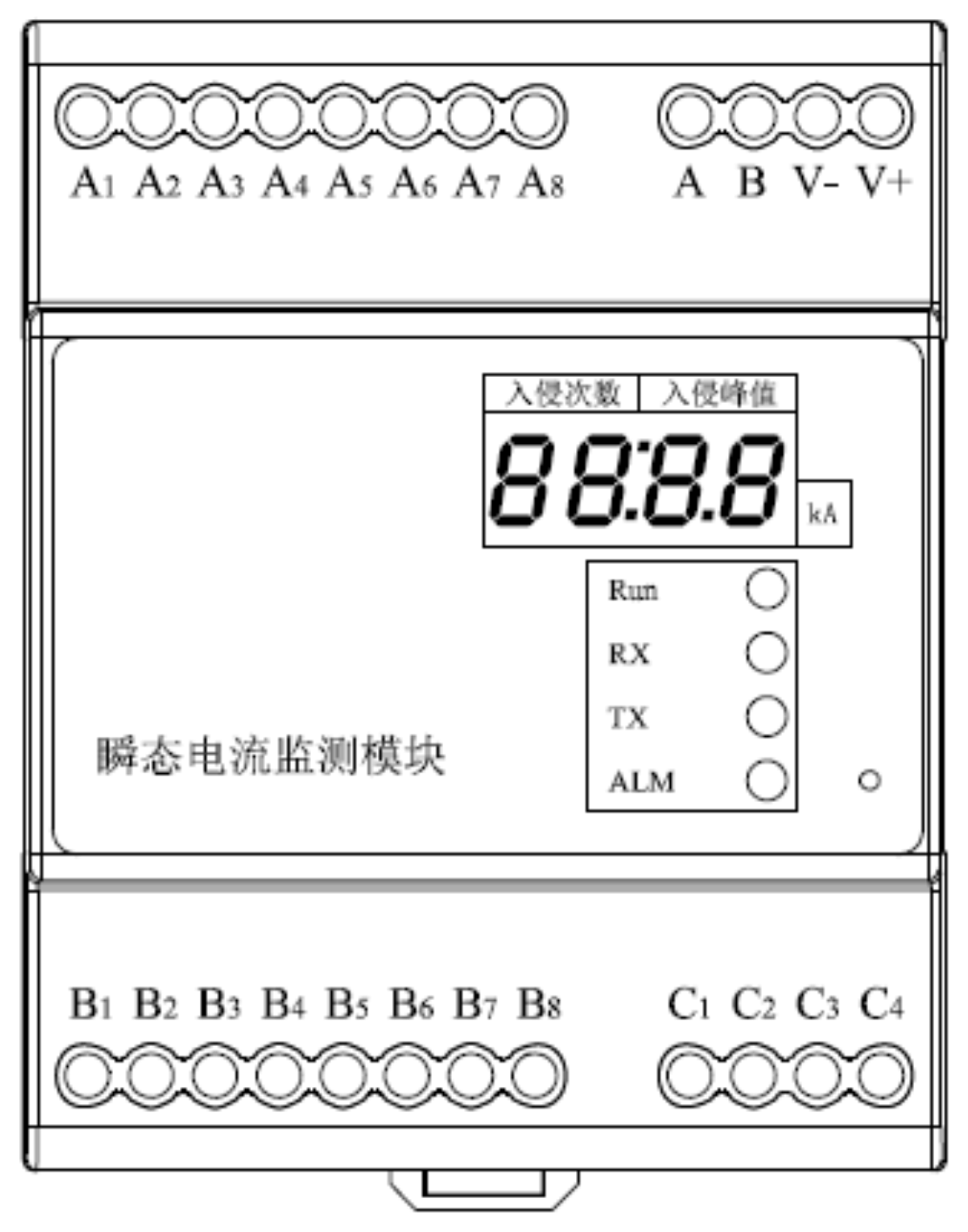
Interface Definition
| No. | Definition |
|---|---|
| 1 | V+, V-: Power Supply Input 5V DC (when 220V Power Supply is used, this interface does not need Power Supply) |
| 2 | A,B:RS485 Bus Interface |
| 3 | A3, A4: Power Supply Input 220V AC, A3-Live Wire, A4-Neutral Wire |
| 4 | C1, C2: C1-Rogowski coil core wire, C2-Rogowski coil shielding layer wire |
| 5 | Antenna interface: when wireless communication is used, the antenna interface is at the bottom of the module |
| 6 | Ethernet port: when Ethernet communication is used, the network port is at the top of the module |
Key Points
- Definition: The FL Transient Current Monitor is FEXLINK's online monitoring device for lightning current and transient overcurrent, capable of recording surge waveforms and peak values.
- Core Capabilities: High-bandwidth sampling captures transient current waveforms and records peak value, polarity and timestamp, enabling lightning event traceback and statistical analysis.
- Scenarios: Suitable for lightning protection acceptance testing, lightning event traceback and SPD effectiveness evaluation.
- Related Products: FSS Smart SPD, Outdoor Lightning Current Monitor, FG Smart Gateway.
Frequently Asked Questions
Product FAQ
What is FL Transient Current Monitor?
The FL Transient Current Monitor is FEXLINK's online monitoring device for lightning current and transient overcurrent, capable of recording surge waveforms and peak values.
What scenarios does FL Transient Current Monitor apply to?
Suitable for lightning protection acceptance testing, lightning event traceback and SPD effectiveness evaluation.
How does FL Transient Current Monitor differ from traditional solutions?
Unlike ordinary lightning counters that only record event counts, the FL records full waveforms and peak parameters for event traceback and mechanism analysis.
How is FL Transient Current Monitor installed and integrated?
Clamp the Rogowski coil onto the busbar under test, connect the main unit to the RS485 bus, and configure the trigger threshold.
How can I purchase FEXLINK products or request a demo?
Submit requirements via the Contact page on the FEXLINK website, or call +86-755-8653-6148 to request a demo and selection consultation; engineers will propose a matched solution and quotation based on your scenario.
FEXLINK Business Scope
FEXLINK 微物联,专注配电场景电气安全与数字能源技术研发。我们以多维精准感知与智能算法为核心,通过端侧感知芯片、多维电气时序特征算法、三层电碳大模型,实现雷电防护、接地监测、电气隐患识别;同步完成配电计量、电能质量分析、回路级碳排核算。面向老旧柜体与工业配电,构建从现场采集、本地芯片推理到云端电碳智能中枢的端云协同体系,赋能能源安全管控、能效优化与低碳数字化落地。