
FS SPD Monitoring Module - surge protector
Real-Time Acquisition of SPD leakage current, temperature, voltage, Lightning Strike count, telemetry and grounding status, covering core degradation indicators
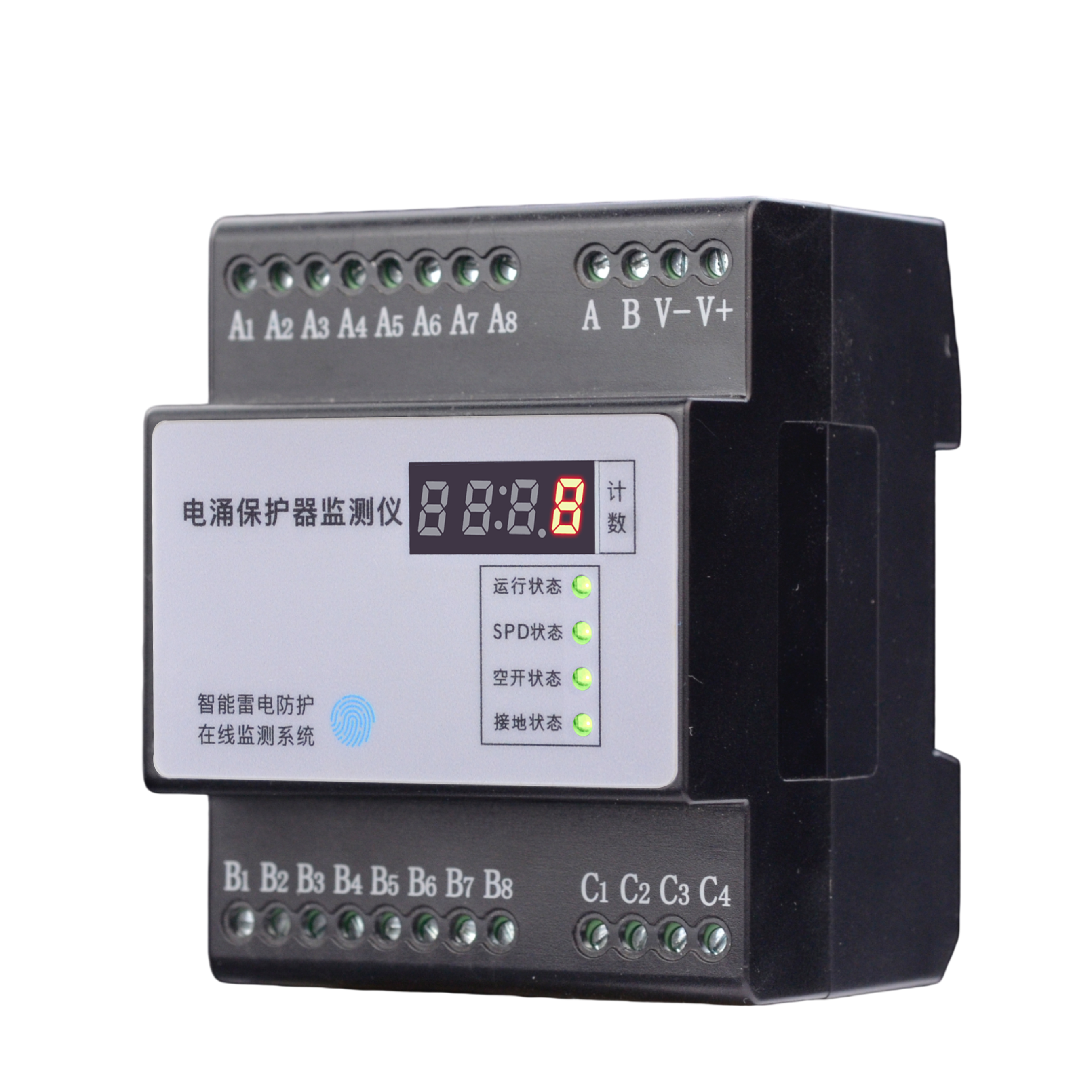
The FS SPD Monitoring Module provides Real-Time Acquisition of SPD leakage current, temperature, voltage, Lightning Strike count, telemetry and grounding status, covering core degradation indicators to replace manual inspection. It monitors the status of Surge Protective Devices (SPDs), typically installed indoors adjacent to the SPD.
Product Overview
The FS SPD Monitoring Module provides Real-Time Acquisition of SPD leakage current, temperature, voltage, Lightning Strike count, telemetry and grounding status, covering core degradation indicators to replace manual inspection. It acquires leakage current, SPD temperature and ambient temperature, SPD damage status, MCB trip status, SPD false-grounding and poor-grounding status, and SPD lightning discharge count.
It monitors the status of Surge Protective Devices (SPDs), typically installed indoors adjacent to the SPD. Supports RS485 (Modbus), Zigbee, and Ethernet (Modbus TCP/MQTT) communication, enabling integration with local monitoring or cloud platforms.
Core Capabilities
- 3-channel leakage (50~1500μA) and 2-channel temperature (-20~105℃) high-precision measurement.
- Lightning strike count minimum trigger 0.1kA, count range 0~9999 times, intuitive local digital tube display.
- Estimates remaining lifespan (0~100%) based on monitoring data, providing advance replacement warnings.
- SPD, MCB, and grounding status indicator lights independently flash red for alarms, with configurable thresholds.
Product Features
Full-Parameter Monitoring
Supports 3-channel leakage (50~1500μA) and 2-channel temperature (-20~105℃) high-precision measurement, accurately sensing SPD performance degradation.
Leakage/Temperature Dual Acquisition
3-channel leakage current and 2-channel temperature independent monitoring, covering core SPD degradation indicators for accurate health assessment.
Precise Lightning Strike Count
Minimum trigger 0.1kA, count range 0~9999 times, intuitive local digital tube display for easy statistics of lightning frequency and lifespan assessment.
Lifespan Prediction & Early Warning
Estimates remaining lifespan (0~100%) based on monitoring data, providing advance replacement warnings to avoid fire or equipment damage caused by SPD failure.
Local Acoustic-Optical Alarm
SPD, MCB, and grounding status indicator lights independently flash red for alarms, with configurable thresholds, enabling quick on-site fault localization without backend queries.
Multi-Protocol Flexible Networking
Supports RS485 (Modbus), Zigbee, and Ethernet (Modbus TCP/MQTT), enabling integration with local monitoring or cloud platforms.
Selection Guide
Model Naming Convention
| Model | Installation Environment | Telemetry/MCB/Grounding/Count | Leakage Monitoring | Temperature Monitoring | Voltage Monitoring | Lifespan Estimation | Communication Method |
|---|---|---|---|---|---|---|---|
| FS-00011-R | Indoor | Supported | --- | --- | --- | --- | RS485 Modbus |
| FS-00011-Z | Indoor | Supported | --- | --- | --- | --- | Zigbee Modbus |
| FS-00011-E | Indoor | Supported | --- | --- | --- | --- | Ethernet Modbus TCP/MQTT |
| FS-03211-R | Indoor | Supported | 3-channel | 2-channel | --- | Supported | RS485 Modbus |
| FS-03211-Z | Indoor | Supported | 3-channel | 2-channel | --- | Supported | Zigbee Modbus |
| FS-03211-E | Indoor | Supported | 3-channel | 2-channel | --- | Supported | Ethernet Modbus TCP/MQTT |
| FS-33211-R | Indoor | Supported | 3-channel | 2-channel | 3-channel | Supported | RS485 Modbus |
| FS-33211-Z | Indoor | Supported | 3-channel | 2-channel | 3-channel | Supported | Zigbee Modbus |
| FS-33211-E | Indoor | Supported | 3-channel | 2-channel | 3-channel | Supported | Ethernet Modbus TCP/MQTT |
Technical Parameters
Basic Parameters
| Operating Voltage | DC 9~27V |
| Power Consumption | 1W |
| Operating Temperature | -20℃~60℃ |
| Operating Humidity | <95% |
| Product Weight | 260g |
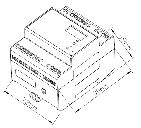
| Dimensions | 72*90*69mm (L*W*H) |
| Enclosure Material | Thermoplastic UL94V0 |
| Protection Rating | IP20 |
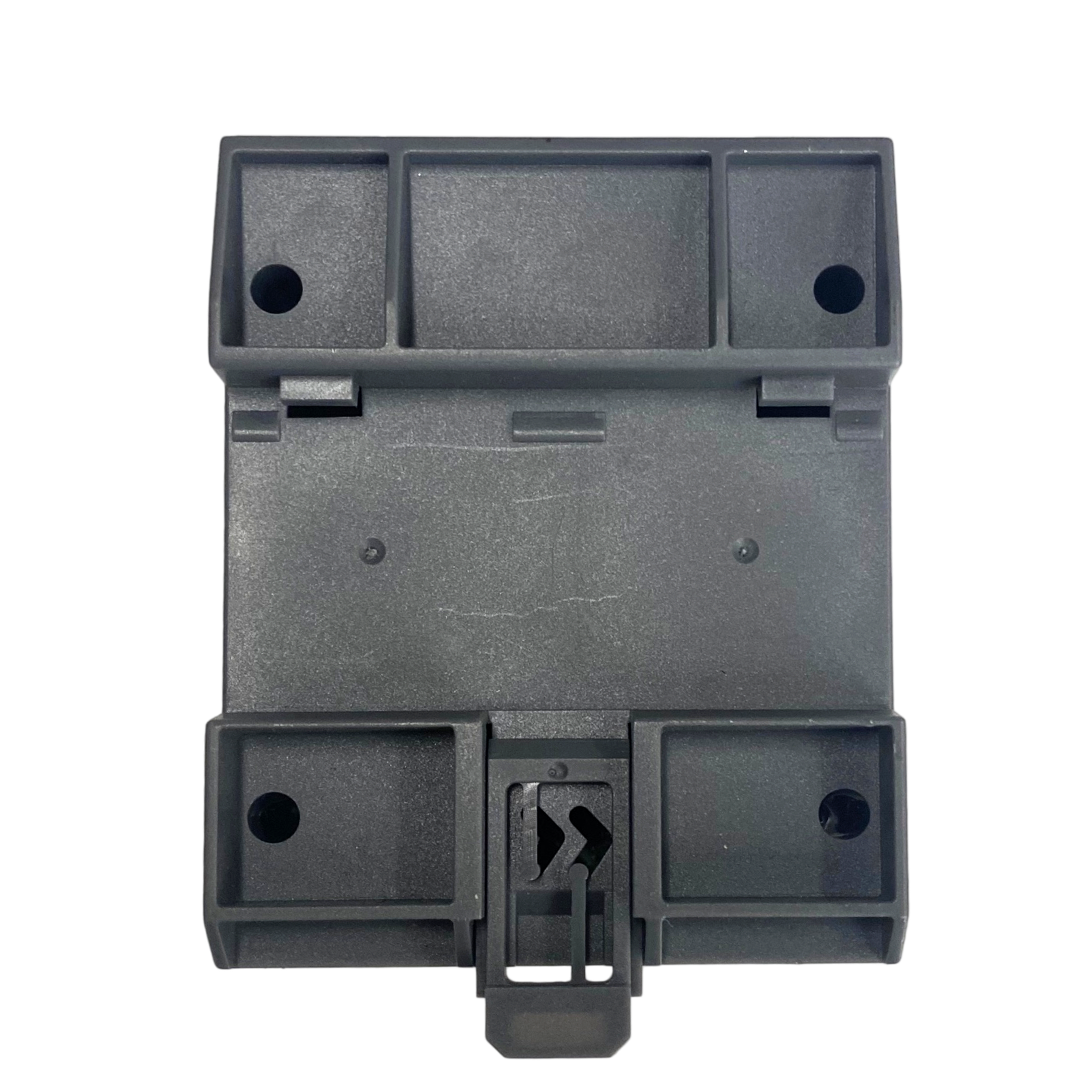
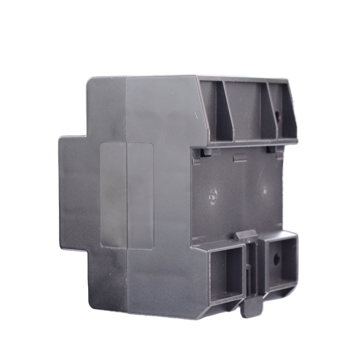
| Installation Method | Standard 35mm DIN-rail |
Smart Monitoring Functions
| Communication Method | RS485/Zigbee/Ethernet |
| Communication Protocol | Modbus Protocol/MQTT Protocol |
| Lightning Strike Count | 0~9999 times, minimum trigger 0.1kA |
| Status Monitoring | SPD telemetry grounding status, MCB status |
| Temperature Acquisition | -20.0~105.0℃, ±0.5℃ |
| Leakage Current Acquisition | 50.0~1500.0μA, ±10μA |
| Voltage Acquisition | 0~600.0V, ±1V |
| Lifespan Estimation | 0~100.0% |
Installation Instructions
Installation Dimensions
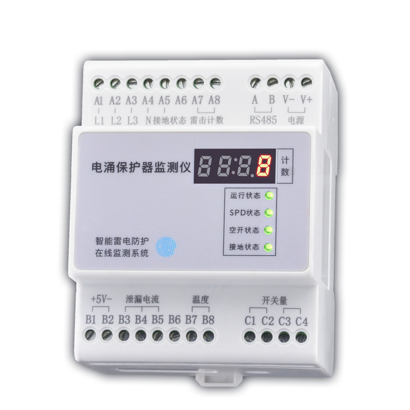
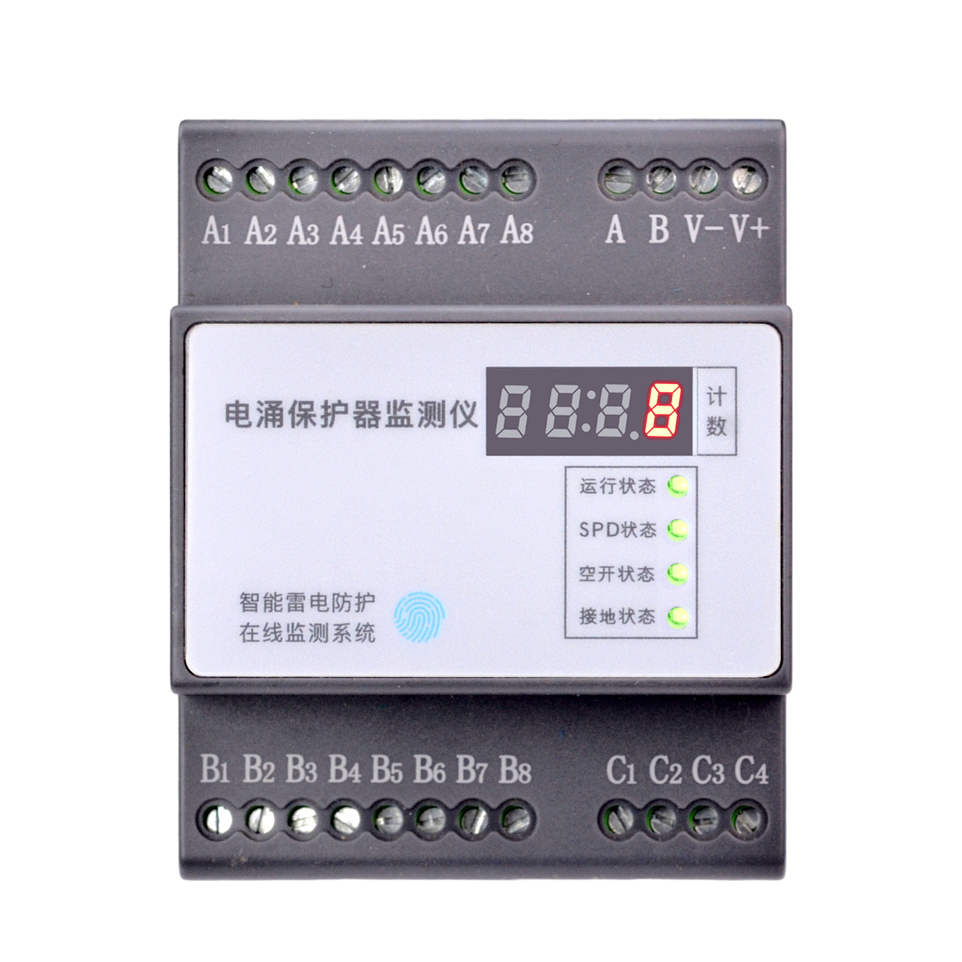
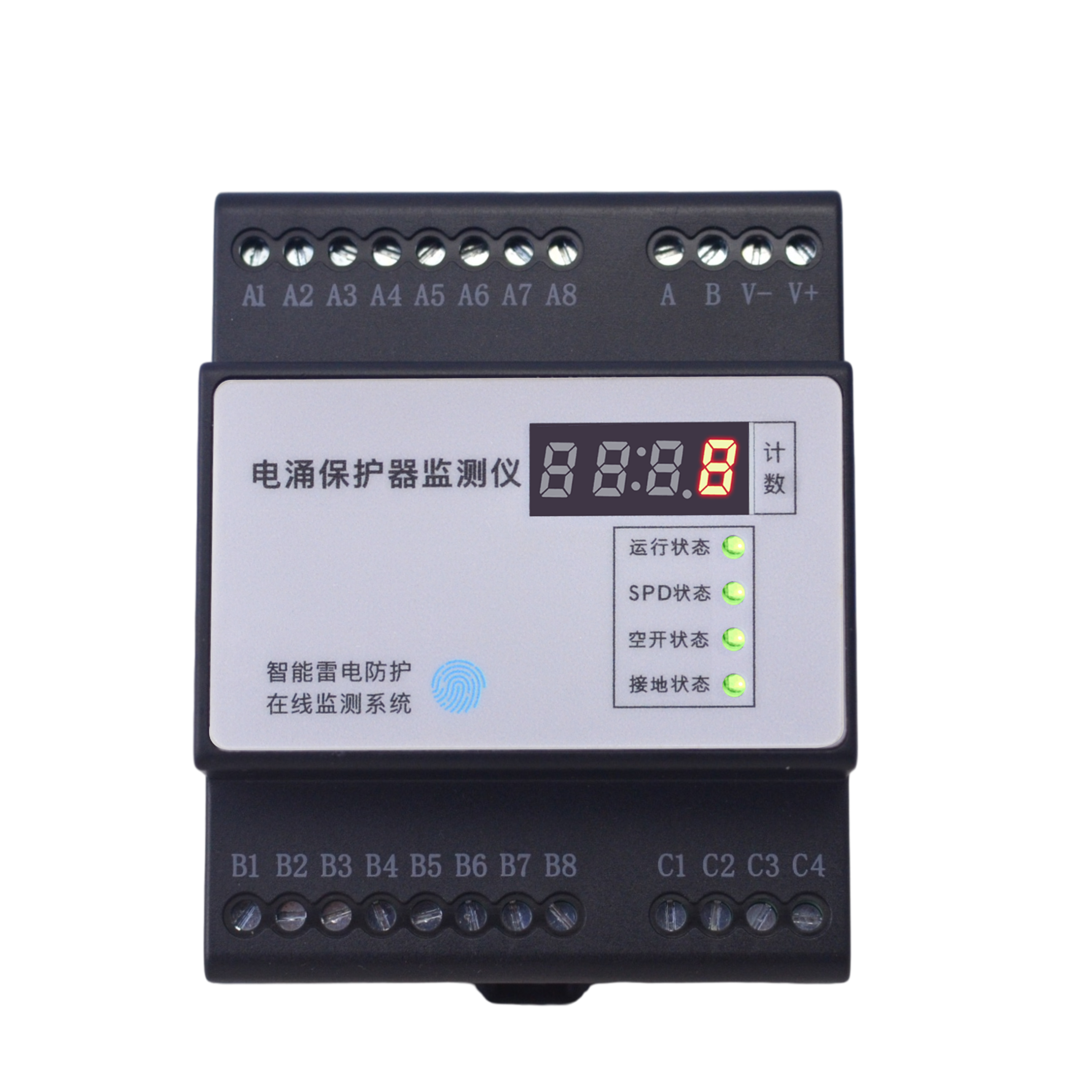
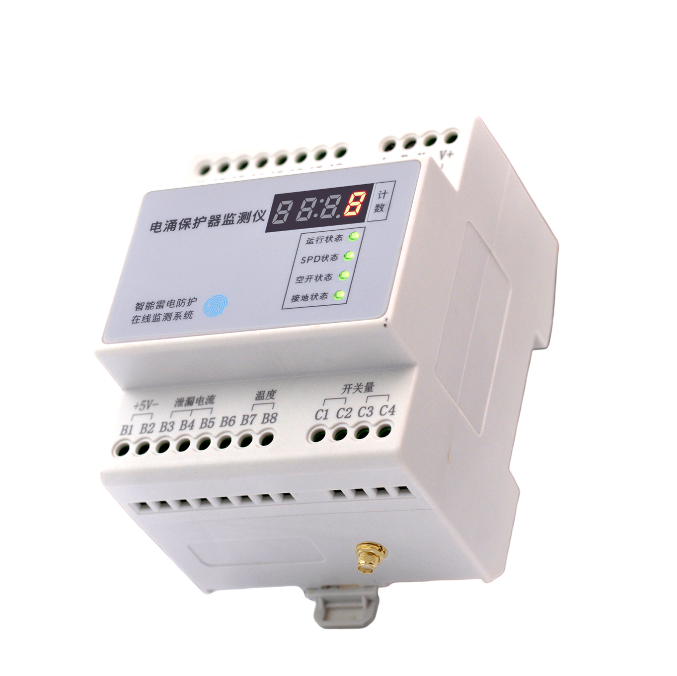
Interface Description
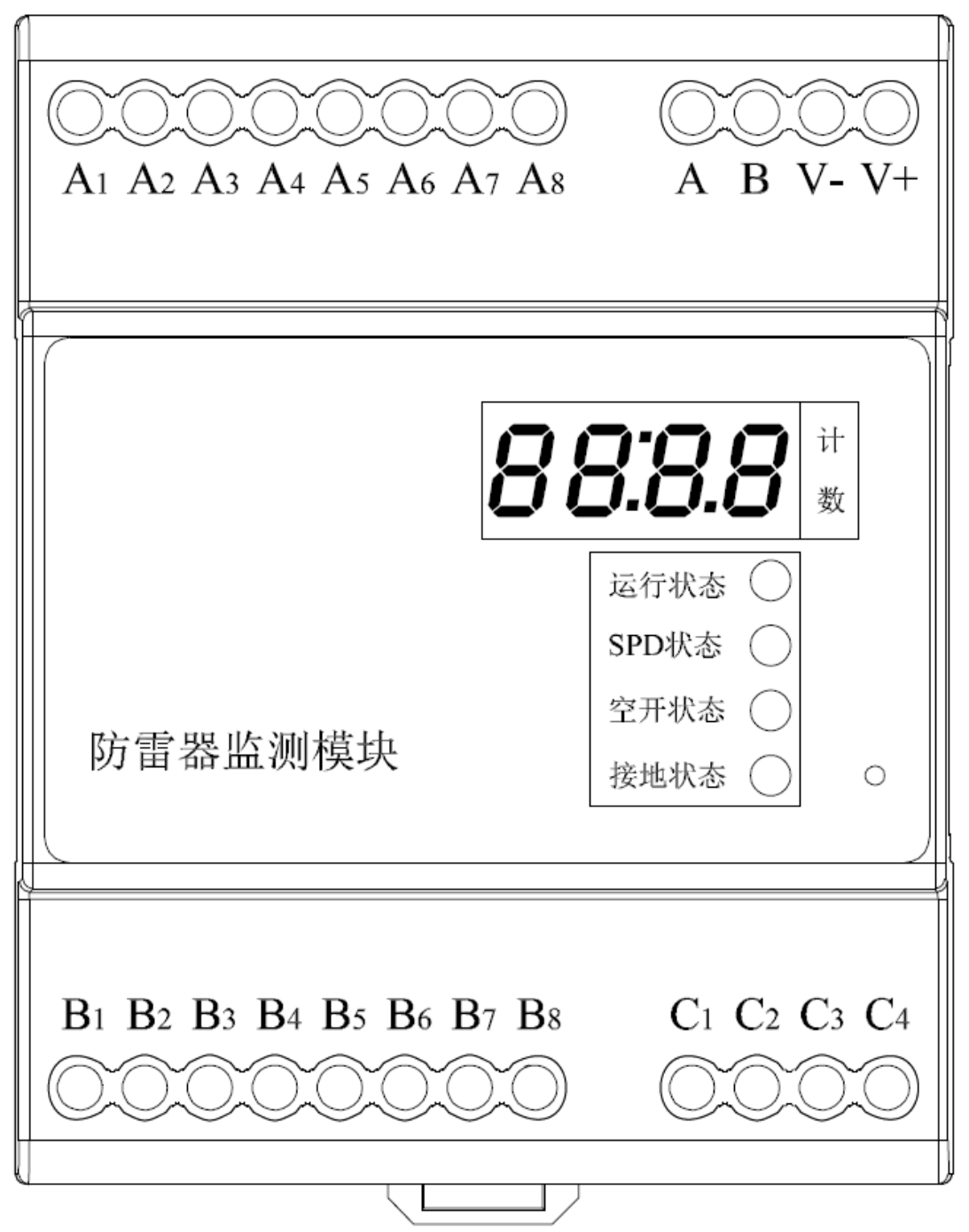
Interface Definition
| No. | Definition |
|---|---|
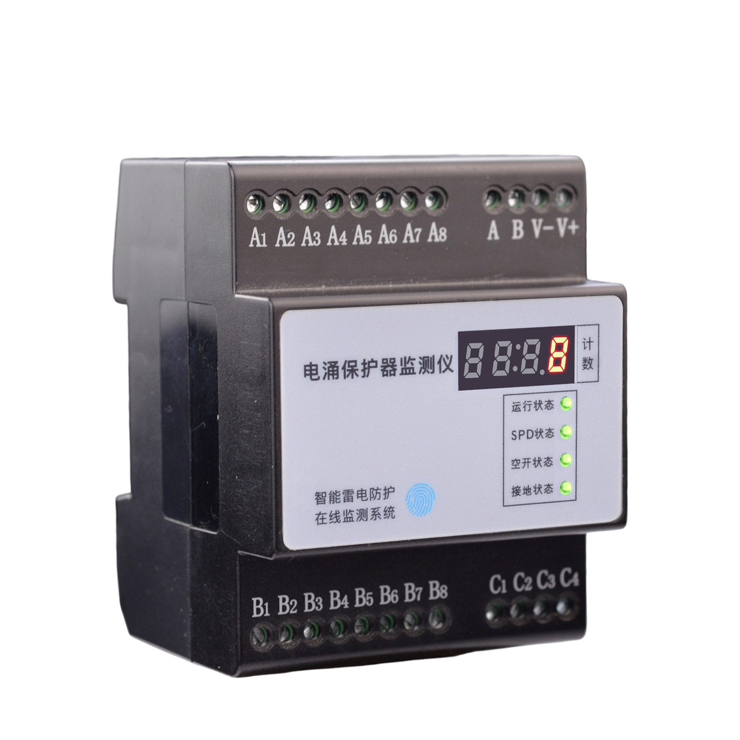
| 1 | V+, V-: DC12V power input |
| 2 | A, B: RS485 bus interface |
| 3 | A1~A5: A1-L1, A2-L2, A3-L3, A4-N, A5-PE, used for monitoring each phase voltage and grounding status |
| 4 | A7, A8: Lightning strike count coil input (no polarity) |
| 5 | B1, B2: B1-5V, B2-0V, Power Supply for leakage current coil and temperature sensor |
| 6 | B3, B4, B5: Channel 3/2/1 leakage current signal, connected to yellow signal wire of leakage coil |
| 7 | B7, B8: Channel 2/1 temperature signal, connected to yellow signal wire of temperature sensor |
| 8 | C1, C2: Used for monitoring MCB status (digital), no polarity |
| 9 | C3, C4: Used for monitoring SPD telemetry status (digital), no polarity |
| 10 | Antenna interface: For wireless communication, the module has an antenna interface at the bottom |
| 11 | Ethernet port: For Ethernet communication, the module has an RJ45 port at the top |
Key Points
- Definition: The FS SPD Monitor is FEXLINK's standalone SPD monitoring module that acquires SPD leakage current, temperature, voltage, lightning count, telemetry and grounding status in real time.
- Core Capabilities: Retrofits onto any brand of SPD to deliver multi-dimensional monitoring of leakage, temperature, lightning count and telemetry; supports RS485/MQTT upload.
- Scenarios: Suitable for upgrading existing distribution-cabinet SPDs to online monitoring without replacing the original SPD.
- Related Products: FSS Smart SPD, FSP Smart SPD Base, FG Smart Gateway.
Frequently Asked Questions
Product FAQ
What is FS SPD Monitor?
The FS SPD Monitor is FEXLINK's standalone SPD monitoring module that acquires SPD leakage current, temperature, voltage, lightning count, telemetry and grounding status in real time.
What scenarios does FS SPD Monitor apply to?
Suitable for upgrading existing distribution-cabinet SPDs to online monitoring without replacing the original SPD.
How does FS SPD Monitor differ from traditional solutions?
Compared with replacing integrated smart SPDs, the FS monitor retrofits onto existing SPDs at lower cost and with less installation impact.
How is FS SPD Monitor installed and integrated?
Mount on a standard 35mm DIN rail, connect the sensing wires to the SPD telemetry terminals and leakage CT, then wire the RS485 bus.
How can I purchase FEXLINK products or request a demo?
Submit requirements via the Contact page on the FEXLINK website, or call +86-755-8653-6148 to request a demo and selection consultation; engineers will propose a matched solution and quotation based on your scenario.
Related Products
FG Smart Lightning Protection Gateway
Data aggregation, protocol conversion, intelligent linkage, building a smart lightning protection IoT network.
FL Transient Current Monitor
Microsecond response, millisecond computation, high-precision Rogowski coil, expert in transient current high-speed acquisition.
FEXLINK Business Scope
FEXLINK 微物联,专注配电场景电气安全与数字能源技术研发。我们以多维精准感知与智能算法为核心,通过端侧感知芯片、多维电气时序特征算法、三层电碳大模型,实现雷电防护、接地监测、电气隐患识别;同步完成配电计量、电能质量分析、回路级碳排核算。面向老旧柜体与工业配电,构建从现场采集、本地芯片推理到云端电碳智能中枢的端云协同体系,赋能能源安全管控、能效优化与低碳数字化落地。