 FEXLINK Research Institute
The short answer
Reactive power does no work and never becomes heat, so strictly it consumes nothing. But it must be carried by current, and that current heats transformer windings and cable resistance as I²R copper loss — active power, actually billed. It also occupies apparent-power capacity, shrinking what a transformer can deliver. A low power factor therefore hits three ways: an adjustment charge, equipment pushed to its capacity ceiling, and a small nudge to billed demand through line loss, usually under 1%. Compensation is one of the few measures with a deterministic cost and a calculable return — if you measure before you size.
Two ledgers, not one
The line heard in substations is that a low power factor means paying for nothing. Half of it is right; the wrong half explains why so many proposals produce no credible savings.
Reactive power does no work in an ideal element: a capacitor charges and discharges, an inductor builds a field and collapses it, energy shuttles without becoming heat. But it needs current, and the reactive component heats resistance exactly like the active one. Loss is I²R, and both components enter that square. Reactive power does no work; the current carrying it does.
Equating a low power factor with a high bill invites the assumption that capacitors buy savings in proportion to kvar installed. Reactive power consumes two different things: losses, an energy ledger, and occupied capacity, an asset ledger. Different arithmetic, different money.
The power triangle: one side does the work
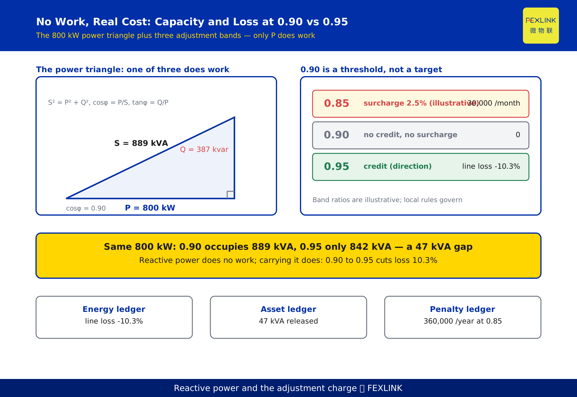
Draw the three powers as a right triangle: active P in kW on the horizontal leg, reactive Q in kvar on the vertical, apparent S in kVA as the hypotenuse. Then S² = P² + Q², with cosφ = P/S and tanφ = Q/P.
Reference case: 800 kW at 0.90. Apparent power is 800 ÷ 0.90 = 889 kVA; reactive power is 800 × 0.4843 = 387 kvar.
Only the 800 kW does work. The 889 kVA is the channel the transformer must hold available; the 387 kvar shuttles inside it. Nameplates are rated in S and ampacity follows I = S/(√3·U), so adequacy is decided by S, not P. At the same 800 kW, 0.90 needs 889 kVA and 0.95 needs 842 kVA — 47 kVA occupied, unusable, and paid for.
Current first, loss second: the square law
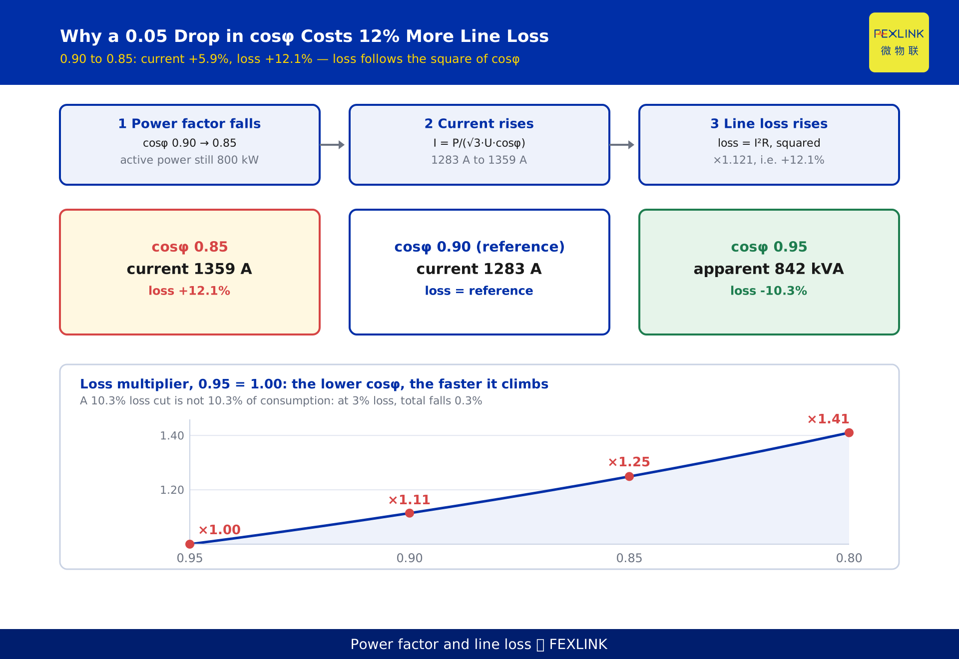
Current relates to power factor as I = P/(√3·U·cosφ). With active power and voltage constant, current is inversely proportional to cosφ; loss is I²R, so loss is inversely proportional to its square.
| Power factor cosφ | Loss multiplier | Change vs 0.95 |
|---|---|---|
| 0.95 | 1.00 | reference |
| 0.90 | 1.11 | +11% |
| 0.85 | 1.25 | +25% |
| 0.80 | 1.41 | +41% |
Each step is 0.05, but the multiplier climbs 1.11 to 1.25 to 1.41 — the penalty accelerates. In the reference case, 0.90 down to 0.85 raises current from 1283 A to 1359 A, up 5.9%, and raises loss 12.1%. The other way, 0.90 up to 0.95 drops apparent power from 889 kVA to 842 kVA, (889/842)² = 1.115, and loss falls 10.3%.
One caution: a 10.3% cut in line loss is not a 10.3% cut in consumption. Line loss is a few percent of the total; at 3%, the reduction is about 0.3%. The value sits in capacity, in the adjustment charge and in transformer temperature rise, not in that 0.3%.
Capacity that reactive power occupies
A transformer is rated in apparent power. How much active power a 1000 kVA unit delivers depends on power factor:
- 0.80: up to 800 kW, with 200 kVA occupied
- 0.90: up to 900 kW, with 100 kVA occupied
- 0.95: up to 950 kW, with 50 kVA occupied
Compensating from 0.80 to 0.95 releases 150 kW from the same transformer — no new equipment, no capacity application, no outage.
What it does not do is cut the monthly bill. Where the demand charge is levied on transformer capacity, you pay for what you declared; compensation changes that only if it lets you surrender capacity or retire a transformer. What it buys is the avoidance of an upgrade — application, equipment, civil works, outage, approval queue — typically an order of magnitude above a capacitor bank. Where load factor sits above 80% and power factor below 0.90, compensate first.
The adjustment charge: 0.90 is a threshold, not a target
The adjustment charge is assessed on the monthly weighted average power factor: above the standard earns a credit, below it a surcharge, in bands. Most large industrial users are assessed at 0.90; some at 0.85 or 0.80, depending on tariff class and voltage.
0.90 is a threshold, not a target. At exactly 0.90 nothing is credited and nothing charged; credit starts at 0.91, surcharge at 0.89. Treating 0.90 as the goal parks the site on the edge of the penalty: one month of load swings and the average lands at 0.88 or 0.87.
Order of magnitude: 1.2 million in monthly energy charges, a weighted power factor of 0.85, and a 2.5% surcharge from the local schedule (illustrative — bands differ and local rules govern) means 30,000 extra that month, 360,000 across a year, producing nothing. The base is normally energy plus demand charges, government funds excluded; take numbers from the local rules, not another region's table.
What compensation cannot fix: the demand charge
A widely repeated claim is that compensation lowers the demand charge. It does not.
Where demand is billed on maximum demand, the quantity is the highest 15-minute average active power in the month. Compensation changes Q, not P, so the reading barely moves. The only path is line loss: a 10.3% cut in loss does lower active power at the meter, but loss is a few percent of load, so the effect is under 1% and invisible.
For a site billed on maximum demand, count three benefits: line loss, the adjustment charge, released capacity. Write demand reduction into a proposal and acceptance will not reconcile. Cutting demand means production shifting, storage, load sequencing — a separate ledger.
One cost never reaches the bill: reactive current raises winding and cable temperatures and ages insulation faster. Winding loss scales with the square of current, so years a few degrees hotter shorten service life.
Sizing the bank: one formula, three traps
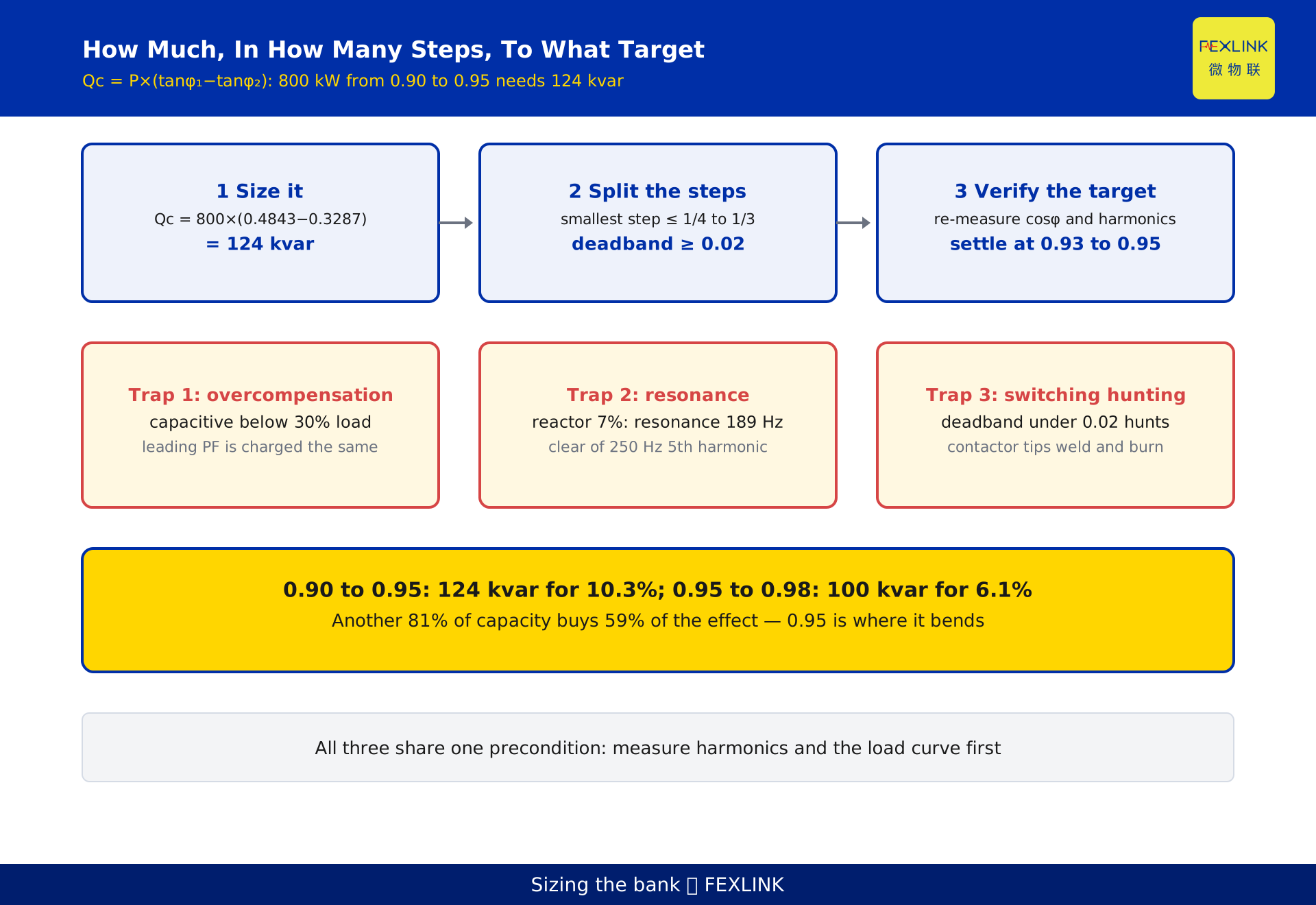
Qc = P × (tanφ₁ − tanφ₂), with φ₁ the angle before compensation and φ₂ the target. In the reference case, tan(acos 0.90) = 0.4843 and tan(acos 0.95) = 0.3287; the difference is 0.1556, and 800 kW × 0.1556 = 124 kvar.
Three traps. First, P is active power at the compensation point, not the nameplate: a 1000 kVA transformer may carry only 500 kW, and sizing on 1000 doubles the bank and guarantees overcompensation at light load. Second, each transformer is calculated separately — where two units do not run in parallel on the low-voltage side, reactive power cannot transfer, and one bank cannot serve both. Third, where load swings, split Qc into steps; keep the smallest below one quarter to one third of the total and the deadband at 0.02 or wider, or the controller will hunt around the threshold.
Why 0.95: where the marginal return bends
0.95 is the usual target not because a standard says so but because the marginal return flattens there.
From 0.90 to 0.95: 124 kvar, line loss down 10.3%, apparent power down 47 kVA. From 0.95 to 0.98: tan(acos 0.98) = 0.2031, so 800 × (0.3287 − 0.2031) = 100 kvar more, for a further 6.1% of loss. Another 81% of capacity buys 59% of the effect.
Two forces work against you. Below about 30% load a fixed bank drives the power factor leading, reactive power flows back, the adjustment still applies, and the penalty arrives from the other side. Compensation also raises end voltage, so iron loss edges up — far smaller than the copper saved, but it eats into the gain at light load.
Take 0.93 to 0.95: 0.95 where load is stable and a credit exists, 0.93 where it swings. Targeting 0.98 or 1.00 is usually about earning a credit rather than saving energy, and needs its own arithmetic.
Three ways to get compensation wrong
Overcompensation. A bank sized for maximum load turns capacitive at light load: the power factor reads leading and is charged just the same, end voltage rises and shortens the life of lighting and electronics, and the switching device operates far more often.
Resonance. A parallel bank resonates with system inductance at n ≈ √(Ssc/Qc). A harmonic landing near that order is amplified several-fold to tenfold, and capacitors overheat, bulge or burst. A 7% series reactor moves resonance to 1/√0.07 ≈ 3.78, around 189 Hz, below the 5th harmonic at 250 Hz. The reactor raises capacitor voltage about 7%, so select for the elevated voltage.
Switching oscillation. Steps too large or a deadband too narrow make the controller hunt around the threshold; welded contactor tips and capacitors hit by repeated inrush are the result.
All three share one precondition: know the harmonic profile and load curve.
Measure first: three quantities, one point, one window
Power factor. Monthly weighted average, not instantaneous; instantaneous values sag at light load and always oversize the bank.
Harmonics. Above 5% total voltage harmonic distortion — the 380 V limit in GB/T 14549 — consider a series reactor; at higher distortion calculate the harmonic current the capacitor can withstand. Where zero-sequence components such as the 3rd harmonic appear, the connection changes too.
Voltage imbalance. Phase currents differ, so loss from the average current understates the real figure, and only per-phase compensation is effective. Correct severe imbalance first.
The SFE power-quality controller (SFE-11111 to 11161-E/G, 3×5A to 3×1000A, WAN or 4G, with phase and harmonic monitoring) gives power factor, harmonics and phase from one device; the ESB three-phase imbalance monitor (ESB-22111 to 22161-R, 3×220/380V, RS485 Modbus, phase only) is cheaper where harmonics are not needed; the ESE monitor covers the 2nd to 31st order at ±1%. With data in hand, the C-01 model in the Tianyan engine's C block returns capacity and step recommendations. Measure again after commissioning — skip it and everything before was wasted.
FAQ
Does reactive power count as energy consumption?
It does no work and does not become heat, so strictly it consumes nothing. But transporting it takes current, and the I²R loss is active power — real money. Here, 0.90 to 0.95 cuts line loss by 10.3%.
The capacitors are installed, so why has the bill barely moved?
Three reasons, in order of likelihood. The site was already above 0.90, so no surcharge to remove. Or demand is billed on maximum demand, which compensation cannot touch. Or line loss is a small share, so a 10.3% reduction lands under 1% of total energy. Judge on weighted power factor and line-loss energy, not the total bill.
Is 1.00 the cheapest target?
No. Reaching 0.98 instead of 0.95 takes about 100 kvar more and cuts line loss only another 6.1%; at light load it also invites overcompensation, and leading reactive power is assessed just the same. The balance point sits near 0.95.
Can capacitors be installed where harmonics are high?
Yes, with a series reactor. A 7% reactor moves resonance to about 189 Hz, clear of the 5th harmonic, and the capacitor's rated voltage must suit the elevated voltage. Above 5% distortion, calculate harmonics first and size second — the order cannot be reversed.
Can two transformers share one bank?
Not unless they run in parallel on the low-voltage side. Reactive power does not transfer across transformers, so capacity belongs where the compensation point is: calculate, install and switch separately.
Scope and limitations
- The mechanism and arithmetic here apply to industrial and commercial users supplied at 10 kV/0.4 kV on two-part tariffs. Single-part tariff users need only the line-loss and capacity parts.
- The 0.90 standard follows the prevailing power factor adjustment rules; some users are assessed at 0.85 or 0.80. Band ratios and charging bases differ by region, and the local supply authority's rules govern.
- The loss multiplier table is derived from I = P/(√3·U·cosφ) and I²R, assuming active power and voltage are unchanged. Voltage does rise slightly with compensation, so the multipliers carry a small deviation.
- The 5% limit for total voltage harmonic distortion at 380 V is quoted from GB/T 14549; shunt capacitor installations follow GB 50227.
- The values 800 kW, 0.90, 0.95, 889 kVA, 387 kvar, 124 kvar, 1.2 million, 2.5%, 30,000 and 360,000 are constructed examples. They are internally consistent and do not represent any real customer or project.
- Model numbers and specifications for the SFE, ESB and ESE units and the Tianyan C-01 model are subject to the current selection manual and product knowledge base; nothing here is a procurement recommendation.
Frequently Asked Questions
Does Reactive Power Actually Waste Energy
Reactive power does no work and never becomes heat, so strictly it consumes nothing