 FEXLINK Research Institute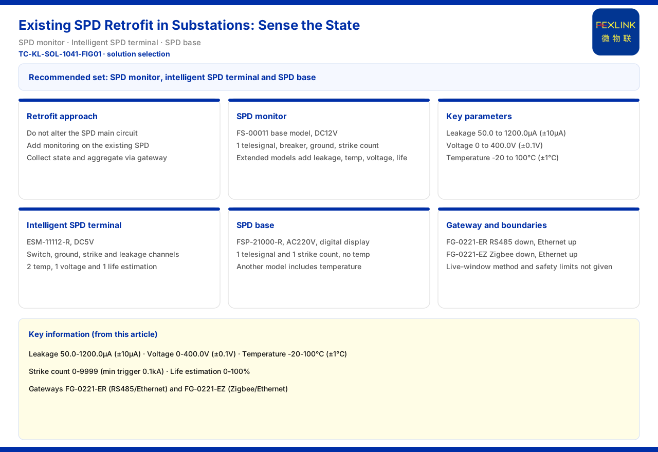
Direct Answer
Adding monitoring to existing SPDs at a substation inside a no-outage window comes down to splitting the work into two things: leave the body untouched and collect status externally. The electrical main circuit of the original surge protective device is not modified; instead, monitoring devices or a base with status-collection capability are added to the existing SPD, so that status quantities such as remote signalling, surge counts, leakage current, temperature and voltage are collected and then aggregated to the cloud through a lightning-protection smart gateway. The combination recommended by the product knowledge base for the "surge protective device status monitoring (existing SPD retrofit)" scenario is exactly three product types: surge protective device monitor, intelligent lightning-protection monitoring terminal and SPD lightning-protection base. As for the concrete construction method, the live-working safety boundary, the zone-by-zone and batch-by-batch sequence, and the window duration for the high-voltage yard no-outage window, the product knowledge base gives none of them and does not cover them, so those points must follow on-site operating rules and professional plans and cannot be inferred from the product materials.
The Basic Approach: Keep the Body Untouched, Collect Status Externally
The biggest constraint in retrofitting existing installations is that the original SPD still carries its protection duty, and its protective function must not be weakened just to add monitoring. The path recommended by the product knowledge base reflects exactly the idea of keeping the body untouched and collecting status externally: status is obtained through an independent monitoring device or an add-on base rather than by replacing the SPD body. For a substation, the value of this approach is that the retrofit action is confined to the secondary side, touching the primary main circuit as little as possible and thereby reducing the impact on operation. Understanding this makes clear why the product knowledge base places the monitoring devices at the centre of its selection guidance instead of suggesting replacement of the whole lightning-protection installation.
First Choice: Surge Protective Device Monitor
Among the FS surge protective device monitors in the product knowledge base, the basic model of the surge protective device monitor (FS-00011) is DC12V and provides 1 remote-signalling channel, 1 air-switch status, 1 grounding status and 1 surge counter. On that basis, the extended models add leakage current, temperature, voltage and life-estimation capability. Its key parameters are: leakage current 50.0 to 1200.0μA (accuracy ±10μA), voltage 0 to 400.0V (±0.1V), temperature -20 to 100℃ (±1℃), surge count 0 to 9999 (minimum trigger 0.1kA), and life estimation 0 to 100%. These parameters show that the monitor covers the status quantities most often watched on an SPD. For a retrofit, if the only need is to know whether it has operated, whether grounding is normal and how many times it has operated, the basic model suffices; if degradation trend must also be seen, an extended model with leakage-current and temperature capability should be chosen.
Second Choice: Intelligent Lightning-Protection Monitoring Terminal
The ESM intelligent lightning-protection monitoring terminal in the product knowledge base provides all-parameter SPD monitoring capability. Its representative model, the intelligent lightning-protection monitoring terminal (ESM-11112-R), uses DC5V and provides 2 digital inputs, 1 grounding channel, 1 surge channel, 1 leakage-current channel, 2 temperature channels, 1 voltage channel and 1 life-estimation channel; there is also a model powered by AC220V. Compared with the monitor, it concentrates the status quantities into a single terminal and is suited to points where a fairly complete status is needed at one location. In a retrofit, if the status observation requirement for a group of SPDs is high, this kind of terminal can reduce the number of separately installed devices and make wiring and maintenance easier.
Third Choice: Add-On SPD Lightning-Protection Base
The FSP SPD lightning-protection bases in the product knowledge base provide a base form for adding monitoring to existing SPDs. The representative model, the SPD lightning-protection base (FSP-21000-R), uses AC220V with a digital display and provides 1 remote-signalling channel and 1 surge counter, without temperature; there are also models that include temperature capability. The idea of the base form is to add monitoring capability together with the base, obtaining basic status while changing the electrical connection of the SPD body as little as possible. For sites with limited space, or where in-place installation within the existing mounting structure is preferred, this kind of base is often easier to implement.
How Data Is Aggregated to the Cloud
The collected status quantities must be aggregated. The FG lightning-protection smart gateways in the product knowledge base provide two representative models: the lightning-protection smart gateway (FG-0221-ER) uses RS485 downstream and Ethernet upstream, while the lightning-protection smart gateway (FG-0221-EZ) uses Zigbee downstream and Ethernet upstream; both are DC12V and perform protocol conversion. For a retrofit, the choice can follow the site's downstream bus conditions: where RS485 wiring already exists, the former is more direct; where points are scattered and wiring is difficult, the latter can be used. The gateway unifies the data from several monitoring devices before sending it to the cloud, and this is the last step in producing queryable, alarm-capable data.
How the No-Outage Window Should Be Arranged
This is the point whose boundary needs special explanation. The product knowledge base does not give the construction method, the live-working safety boundary, the zone-by-zone and batch-by-batch sequence, or the window duration for a substation high-voltage yard no-outage window; the related standard clauses are not developed in the product knowledge base either. Therefore how the window is scheduled, whether live working conditions exist, and how to implement it by zone and batch must all be decided by on-site operating rules, live-working specifications and a professional construction plan. What the product materials can provide is "how the monitoring scheme is selected", not "how the construction window is arranged". Keeping the two apart is a precondition for a retrofit project to proceed smoothly.
Why the Recommended Combination Is Three Product Types
The combination recommended by the product knowledge base for existing SPD retrofit is three types: surge protective device monitor, intelligent lightning-protection monitoring terminal and SPD lightning-protection base. The three are not lined up at random; they correspond to different conditions for adding monitoring. The monitor is suited to taking status locally near an existing SPD. The monitoring terminal is suited to points that need a fairly complete status and concentrated collection. The lightning-protection base is suited to cases where basic status is obtained by adding a base. They are options within the same scenario, not a set that must all be used at once. In a retrofit, selecting by the importance of the point, the available installation space and the required depth of observation is more in line with the reality of existing-installation work than a one-size-fits-all approach.
Three Things to Confirm Before Retrofit
Before starting the addition, at least three things should be confirmed first. First, whether the original SPD has usable auxiliary contacts or status outputs, which decides whether status can be taken by dry contact or remote signalling. Second, whether the installation location has a power supply, because different models use different supply voltages and the on-site supply must match the chosen model. Third, whether the data return path is feasible, that is, whether the gateway's downstream bus and upstream network can reach the point. These three correspond to signal, power and communication respectively, and the absence of any one of them will keep the addition from being implemented. Confirming them clearly at the scheme stage can avoid rework during construction.
Scope and Limitations
- This article is limited to what the product knowledge base already states about the recommended combination for existing SPD retrofit, the three representative product types, the key parameters and the gateway aggregation capability, and does not extend to construction methods, safety boundaries or process arrangements that are not listed.
- The figures in this article (leakage current 50.0 to 1200.0μA, voltage 0 to 400.0V, temperature -20 to 100℃, surge count 0 to 9999, minimum trigger 0.1kA, life estimation 0 to 100%, and so on) are quoted according to the figures listed by the product knowledge base and do not constitute a configuration or construction commitment for any specific project.
- The product knowledge base gives no construction or safety content for the no-outage window, so this article makes no inference; the actual retrofit scheme is subject to on-site rules, the professional construction plan and the latest product materials.