 微物联研究院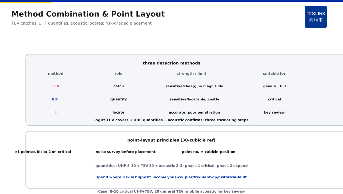
Direct Answer
How should an important distribution room design an online PD (partial discharge) monitoring scheme for its switchgear? The answer: land it in three layers — sensing, edge, platform. The sensing layer uses a "UHF + TEV" combination to monitor discharges inside the cubicles, with acoustic sensing on critical cubicles for locating; the edge layer aggregates data and builds local baselines; the platform layer performs trend analysis and alarm grading, with alarms linked to maintenance work orders. Cover critical cubicles fully, sample general cubicles by risk; the core of the scheme is "continuous monitoring + trend criteria," not a single-shot alarm.
An important distribution room in a campus planned PD monitoring for 30 units of 10 kV switchgear; the initial scheme only installed a TEV inspection instrument (not online) with no backend linkage. Redone with the three-layer scheme: the sensing layer fully covered critical cubicles (incomer, bus coupler, frequently operated) with "UHF + TEV," sampled general cubicles with TEV; the edge layer aggregated data per cubicle and built local baselines; the platform layer performed trend analysis with three-level alarms, auto-generating maintenance work orders. Within three months of go-live, two real PDs were found (growing with load) and maintenance was arranged in advance, avoiding an insulation breakdown. The core of an online PD monitoring scheme is three things: what to measure (method combination), where to place it (sensing points), and how to judge (trend baseline + alarm linkage).
Because:
- A single detection method has blind spots: TEV is sensitive to in-cubicle discharge but cannot measure the true discharge magnitude inside the switchgear; UHF is highly sensitive but costly — a combination covers everything;
- Sensing-point layout determines effectiveness: full coverage of critical cubicles, sampling of general cubicles — spend where risk is highest;
- A single alarm causes false alarms: field interference is heavy; one reading proves nothing — continuous monitoring + local baseline + trend criteria is reliable;
- An alarm without linkage is measurement wasted: alarms must land on maintenance work orders to form a "monitor–alarm–maintenance" closed loop.
Key insight: online PD monitoring is a system engineering task, not "installing a few sensors." Three-layer architecture, method combination, trend criteria, work-order linkage — all four are indispensable.
At one plant, PD alarms were frequent with widely fluctuating single readings, and operators could not tell true from false. After adopting trend criteria: the platform auto-computed local baselines and graded alarms; only alarms exceeding 3× baseline and growing with load reached level 2 or above. In three months there were three real alarms, two confirmed as real defects — the false-alarm rate dropped sharply, and operators stopped running exhausted.
1. Three-Layer System Architecture
The first step: fix the system architecture. Each of the three layers has its role:
Sensing layer (what to measure, where to place):
- Method combination: UHF (ultra-high frequency) + TEV (transient earth voltage) + acoustic (locating on critical cubicles);
- Sensing-point layout: 1–2 points per cubicle; critical cubicles fully covered, general cubicles sampled;
- Data acquisition: continuous online acquisition, capture rate covering discharge events (millisecond triggering).
Edge layer (data aggregation and local judgment):
- Data aggregation: all cubicle data aggregated to the edge gateway (ESX);
- Local baseline: automatic per-cubicle background-noise baseline;
- Local pre-judgment: pre-judgment against baseline; abnormal data cached locally and uploaded;
- Offline capability: local judgment continues during network outage (offline watch).
Platform layer (trend analysis and business closed loop):
- Trend analysis: discharge trend, load–discharge correlation analysis;
- Alarm grading: graded by severity (warning / alarm / critical);
- Work-order linkage: alarms auto-generate maintenance work orders for closed-loop disposition;
- Reports and records: monitoring and disposition records retained.
Relations among the layers:
- Sensing decides "whether data exists";
- Edge decides "whether judgment is fast" (local baseline + offline capability);
- Platform decides "whether disposition flows" (alarm–work-order closed loop).
Key insight: the three-layer architecture is the skeleton. Sensing measures, edge judges fast, platform closes the loop — missing any layer, the scheme is incomplete.
2. Detection-Method Combination and Sensing-Point Layout
The core: how to combine methods and place points.
Detection-method comparison:
- TEV (transient earth voltage): sensitive to in-cubicle discharge, low cost, suitable for full coverage; limitation: cannot measure internal discharge magnitude, affected by background interference;
- UHF (ultra-high frequency): high sensitivity, can locate in-cubicle discharge, suitable for critical cubicles; limitation: higher cost, needs sensor mounting space;
- Acoustic: accurate locating (sound propagation), suitable for review/locating on critical cubicles; limitation: poor penetration, affected by noise.
Method-combination strategy:
- Critical cubicles (incomer, bus coupler, frequently operated, historical-fault): UHF + TEV combination; acoustic added on key cubicles;
- General cubicles: full TEV coverage (low cost, wide coverage);
- Meaning of the combination: TEV catches anomalies, UHF quantifies and reviews, acoustic locates — three escalating steps.
Sensing-point layout principles:
- At least 1 point per cubicle (TEV); 2 for critical cubicles (UHF + TEV);
- Sensors mounted at the front/middle/rear of the cubicle (discharge-prone positions);
- Standardized point numbering (cubicle no.–position), matching the backend ledger;
- Background-noise survey before placement (adjust positions with heavy interference).
Sensing-point quantity reference:
- 30 cubicles: 8–10 critical fully covered (UHF + TEV), 20 general with TEV;
- Sensor totals: 8–10 UHF + 30 TEV + 2–3 acoustic (mobile for key cubicles);
- Phased build: phase 1 critical cubicles, phase 2 general expansion.
Key insight: method combination + point layout decide "measured or not." TEV covers to catch anomalies, UHF reviews key points, acoustic locates — spend where risk is highest.
3. Local Baseline and Trend Criteria
The key: how to judge "real discharge vs interference."
How to build the local baseline:
- Record 24–72 h of background noise continuously after installation (outage / low-load periods);
- Statistically compute the baseline mean and fluctuation range (independent baseline per cubicle);
- Re-measure baselines after environmental change (new VFDs, large equipment);
- Baselines stored at the edge layer so over-baseline judgment has a basis.
How to use trend criteria:
- A single alarm does not count: over 3× baseline triggers a warning;
- Trend shows change: rising discharge trend = real-defect suspicion;
- Correlation shows pattern: grows with load = real defect; appears with operations = transient interference;
- Locating confirms: acoustic/UHF locating to the defect point = confirmation.
Alarm-grading design:
- Level 3 (warning): below 3× baseline, stable trend — continue monitoring;
- Level 2 (alarm): above 3× baseline + rising trend — arrange near-term inspection;
- Level 1 (critical): above 10× baseline + grows with load + locatable — immediate outage inspection.
Meaning of the criteria:
- Trend criteria separate "real discharge" from "background interference";
- False-alarm rate drops, operator trust rises;
- Alarm grading gives the disposition rhythm a basis (neither hasty nor delayed).
Key insight: local baseline + trend criteria are the "brain." Single alarms mislead; continuous monitoring + trend criteria is reliable — baseline, trend, correlation, locating, four in one.
4. Alarm Grading and Work-Order Linkage
The closed loop: how alarms become maintenance.
Alarm-to-work-order flow:
- Platform alarm (level 2+) → auto-generate maintenance work order;
- Work order links cubicle no., sensing point, alarm data (operators have evidence);
- Maintenance executed → result filled back (disposition closed loop);
- Re-measurement confirms → alarm cleared, trend falls back.
Work-order content design:
- Location info: cubicle no., sensing point, mounting position;
- Data attachments: alarm trend, over-baseline magnitude, correlation analysis;
- Suggested actions: acoustic review / outage inspection / continued monitoring;
- Time limits: by alarm level (level 1 immediate, level 2 within a week).
Linkage mechanisms:
- With maintenance planning: level-2 alarms merge into the planned maintenance window;
- With production planning: level-1 alarms coordinate outage windows;
- With ledgers: disposition records retained, history traceable;
- Multi-source linkage: PD alarm + temperature anomaly + current anomaly, multi-signal confirmation.
Linkage verification:
- Alarm-disposition closed-loop rate (alarm–work-order–handling–re-measure);
- False-alarm rate (share confirmed as non-defect on disposition);
- Real-defect discovery rate (share confirmed as defect on work orders).
Interference identification and elimination:
- Common interference: VFDs, motor starts, switch operations, radio signals, poor grounding;
- Identification: discharge-feature comparison (interference waveform vs discharge waveform);
- Correlation analysis: appears with operations = transient interference; grows with load = real defect;
- Elimination: sensor position adjustment, filter settings, baseline re-measurement;
- Only after interference elimination can trend criteria be discussed — otherwise the false-alarm rate stays high.
Key insight: an alarm without linkage is measurement wasted. Alarm → work order → maintenance → re-measure; the loop is where value lies — rhythm by level, records retained throughout.
5. Phased Construction Recommendations
How does the scheme land? Phased construction lowers the threshold.
Phase 1 (critical first):
- Scope: incomer, bus coupler, frequently operated, historical-fault cubicles;
- Method: UHF + TEV combination, acoustic on key cubicles;
- Goal: build baselines, run through the alarm–work-order closed loop;
- Time: complete in 1–2 months.
Phase 2 (expanded coverage):
- Scope: full TEV coverage of general cubicles;
- Method: TEV expansion + edge-layer capacity growth;
- Goal: full-area coverage, false-alarm-rate optimization;
- Time: 3–6 months.
Phase 3 (deepened application):
- Scope: station-wide trend analysis and prediction;
- Method: load–discharge correlation modeling, defect-trend prediction;
- Goal: from "alarm" to "prediction" (maintenance window);
- Time: continuous iteration.
Benefits of phasing:
- Phase 1 delivers quickly (critical cubicles protected first);
- Investment spread (no one-time large outlay);
- Experience accumulation (baselines and false-alarm behavior learned first);
- Scalable (architecture supports later expansion).
On-site implementation points:
- Pre-installation survey: background-noise testing, in-cubicle space assessment, sensor-position confirmation;
- Installation standard: sensors fixed reliably, signal cable shielded and grounded, point numbering registered;
- Commissioning verification: compare with manual detection (PD-instrument patrol) after installation to confirm consistency;
- Training handover: operators learn to read alarms, view trends, grade levels;
- Acceptance criteria: baseline established, alarm–work-order loop running, false-alarm rate below the agreed value.
Key insight: phasing makes the scheme landable. Critical first for quick wins, phase 2 expands coverage, phase 3 deepens prediction — every phase has a goal and verification.
6. Product Landing: Switchgear PD Monitoring Scheme
FEXLINK products bring the switchgear PD monitoring scheme to the field:
- ESX Edge Computing Gateway: aggregates cubicle monitoring data, local baselines, offline judgment during outages;
- EST Multi-Channel Temperature Controller: adds temperature monitoring, PD + temperature multi-signal linkage;
- Digital Electrical Intelligent Supervision System: platform trend analysis, alarm grading, work-order linkage closed loop;
- Sensor combination: TEV/UHF/acoustic configured by cubicle grade (customized scheme);
- The platform outputs three-level alarms (warning / alarm / critical) and auto-generates maintenance work orders.
Design principle in one sentence: upgrade "installing sensors" into a "monitor–judge–dispose" closed-loop system. Three-layer architecture, trend criteria, work-order linkage — landable scheme, measurable results.
7. Common Scheme-Design Mistakes
- Installing sensors without a system: standalone alarms with no backend. Consequence: no one judges false alarms; no one handles alarms. Correct: complete three-layer architecture.
- A single detection method: only TEV or only UHF. Consequence: blind spots or excessive cost. Correct: method combination (TEV + UHF + acoustic).
- Arbitrary point placement: no risk-based grading. Consequence: critical cubicles uncovered, money spent wrong. Correct: full coverage of critical, sampling of general.
- Treating a single alarm as a conclusion: alarm and dispose whenever over threshold. Consequence: extremely high false-alarm rate; operators exhausted. Correct: local baseline + trend criteria.
- Alarm without maintenance linkage: alarms but no work orders. Consequence: monitoring wasted, problems remain. Correct: alarm → work order → maintenance → re-measure closed loop.
Scope and Limitations
This article provides an overall scheme framework for online PD monitoring of 10 kV switchgear (three-layer architecture, method combination, sensing-point layout, trend criteria, work-order linkage) for the scheme design of MV-switchgear PD monitoring projects. Detection-method selection and sensing-point quantity should be adjusted to cubicle type, field interference, and budget; alarm-grading thresholds (e.g., 3×/10× baseline) are engineering experience references and should follow on-site baseline measurement; acoustic locating and outage inspection must be performed per procedures by qualified personnel. Online monitoring data is managed uniformly through the platform to form trend alerts. All cases are anonymized (a certain campus / plant) and do not refer to any specific customer.