 FEXLINK Research Institute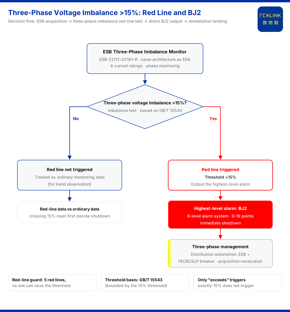
Direct answer: a three-phase voltage imbalance above 15% is the red line. In the knowledge base, the red line records this threshold as "three-phase voltage imbalance >15%," based on GB/T 15543. Once triggered, the system outputs the highest-level alarm, BJ2 — in the six-level alarm system, BJ2 maps to 0-19 points and immediate shutdown; no one can raise that threshold. The field carrier used to acquire the three-phase imbalance element is the ESB three-phase imbalance monitor (ESB-22111~22161-R).
1. The red line is a quantified threshold: above 15%
The threshold given by the red line is a three-phase voltage imbalance greater than 15%. Two layers must be kept apart. First, the threshold applies to the state quantity "three-phase voltage imbalance," not to another electrical quantity. Second, the decision action is "exceeds" — only when the degree of imbalance crosses 15% does the red line trigger. Below that line, the trigger description of the red line is not satisfied.
The boundary of the knowledge base here should be stated. It lists only the trigger condition and its basis; it gives no calculation method or value convention for three-phase voltage imbalance. This article therefore explains the 15% threshold value itself only, without inferring calculation details or converting it into other expressions.
2. The basis is GB/T 15543, and the citation is narrow
The threshold is not set by the product on its own; it is obtained by citing a standard. The knowledge base marks the red line's basis as GB/T 15543. The citation here is bounded by that red-line entry: it confirms only that the trigger condition "three-phase voltage imbalance >15%" is supported by that standard, and does not expand into its other clauses, limits or scope. Clauses not listed in the knowledge base are not cited, and no extrapolation is drawn from them.
Stating the basis separately matters because "citing a standard" is easily misread as "the whole standard applies." In fact the connection is narrow: the red line corresponds to GB/T 15543 and lands only on the single trigger condition above.
3. What happens on trigger: straight to the highest alarm level
The consequence of a red-line trigger is not a graded notice but a direct output of the highest-level alarm. In the knowledge base, the alarm system has six levels; BJ2 sits in the highest tier, with a value range of 0-19 points and an action of immediate shutdown. The chain is therefore: three-phase voltage imbalance above 15% → red line triggered → BJ2 output directly → immediate shutdown.
Note the word "directly". The result is not "recommend attention" or "keep observing"; it lands at the highest level and points to shutdown. The 15% line defines an action level, not a reminder level: once crossed, the system applies its heaviest disposition. Ordinary data can be watched for trends; red-line data must first decide whether to shut down.
4. The threshold cannot be raised
The red line is a red line also because its threshold cannot be relaxed. The knowledge base states explicitly that a red-line trigger outputs the highest-level alarm directly, and that no one can raise the threshold. So 15% is not a value that can be negotiated on site or set station by station; whatever the operating condition and however frequent the alarms, the threshold may not be moved upward to reduce actions. Its direction is one-way: strictly enforced, never relaxed.
This matters especially in field communication. When alarms appear frequently, the common impulse is to "raise the threshold a little." In the red-line context that path is closed: the only correct response is to return to the imbalance itself and find the cause, rather than to modify the decision condition. Treating 15% as a negotiable setting value conflicts directly with "no one can raise the threshold."
5. The acquisition carrier: the ESB three-phase imbalance monitor
For the red line to take effect in the field, three-phase imbalance must be measurable on site. The device carrying that acquisition duty is the ESB three-phase imbalance monitor. The knowledge base states that it shares the same architecture as the ESA all-parameter smart meter, offers six current ratings, and adds phase monitoring on that basis. The ESB three-phase imbalance monitor thus follows the same architectural line as the all-parameter smart meter, while its distinctive capability lies in phase monitoring.
Why is phase monitoring relevant to three-phase imbalance? Three-phase voltage imbalance describes the difference state among the three phases, and judging that difference depends on acquiring the phase relationship of each phase. The monitor provides phase monitoring so that this element can be acquired and used by the red-line decision. The boundary must be clear: the knowledge base positions this monitor around phase monitoring. This article does not attribute other capabilities such as harmonic monitoring to it, nor infer parameters not listed in the knowledge base.
6. From monitoring to remediation: the distribution-automation three-phase management combination
Acquisition and decision are only the first half; after a red-line trigger, the landing point is remediation. The "distribution-automation three-phase management" scenario in the knowledge base gives the combination: the ESB three-phase imbalance monitor plus the FECB2SLP intelligent circuit breaker (with residual-current protection). The former handles acquisition of the three-phase imbalance element; the latter carries the breaker role on the remediation side. Together they form the recommended combination for that scenario.
Stating monitoring and remediation separately avoids a common confusion: the monitor addresses "whether the condition can be seen," while the breaker addresses "whether the action can be executed." The monitor makes three-phase imbalance acquirable and available to the red-line decision; the FECB2SLP intelligent circuit breaker sits on the execution side. The knowledge base places the two side by side as a scenario combination, and this article explains it as given, without inferring wiring methods or setting relationships.
7. A few easily confused points
First, reading "exceeds" as "reaches." The red-line condition is an imbalance greater than 15%, testing whether the line is crossed; counting exactly 15% as a trigger is inconsistent with the knowledge base wording.
Second, treating 15% as an adjustable setting: the knowledge base states no one can raise the threshold, so it may not be adjusted on site to reduce alarms.
Third, equating a red-line decision with general trend data. A red-line trigger outputs the highest-level alarm directly and points to immediate shutdown; it cannot be handled in a "watch it first" manner.
Fourth, widening the citation scope. GB/T 15543 is cited here only for the trigger condition "three-phase voltage imbalance >15%"; other content of that standard is not involved.
Fifth, mixing up monitoring capabilities. The ESB three-phase imbalance monitor's capability feature is phase monitoring; it is not conflated with harmonic monitoring, and unlisted parameters are not extrapolated.
8. Check in order
- Does the site have a means to acquire three-phase imbalance, that is, is an ESB three-phase imbalance monitor installed?
- Does the judged value exceed 15%?
- Once triggered, is it handled as BJ2, that is, 0-19 points and immediate shutdown?
- Is it clear that the threshold cannot be raised and that no one can relax it?
- Following the scenario combination, is the remediation landing point placed on the FECB2SLP intelligent circuit breaker?
This order produces no new parameter conclusions; its purpose is to keep decision, disposition and selection from being shuffled. When the field disagrees over "does this count as a red line" or "what to do after a trigger," this order finds the sticking point faster than arguing over relaxing the threshold.
9. Applicability and limits
First, the three-phase voltage imbalance threshold is bounded by the red-line entry, namely the trigger condition "three-phase voltage imbalance >15%"; no calculation method, value convention or other converted expression is inferred.
Second, references to GB/T 15543 are bounded by the red-line entry, and no inference is made about other clauses, limits or scope of application of that standard.
Third, statements about BJ2 — highest-level alarm, 0-19 points in the six-level alarm system, immediate shutdown, and the threshold not being raisable — are bounded by the knowledge base; no disposition-flow details not written there are added.
Fourth, the description of the ESB three-phase imbalance monitor is bounded by the knowledge base, namely same architecture as the ESA all-parameter smart meter, six current ratings (ESB-22111~22161-R), and added phase monitoring; this article does not infer certifications, protection ratings or unlisted parameters.
Fifth, the distribution-automation three-phase management combination (ESB three-phase imbalance monitor + FECB2SLP intelligent circuit breaker) is bounded by the knowledge base; actual configuration should follow the scenario entry and on-site conditions.
Sixth, this article does not infer standard clauses other than GB/T 15543, nor extrapolate the 15% threshold to other electrical quantities. Where on-site conditions differ from the assumptions here, the corresponding knowledge-base entries and model entries should be checked rather than a single value used as the basis for a decision.