 FEXLINK Research Institute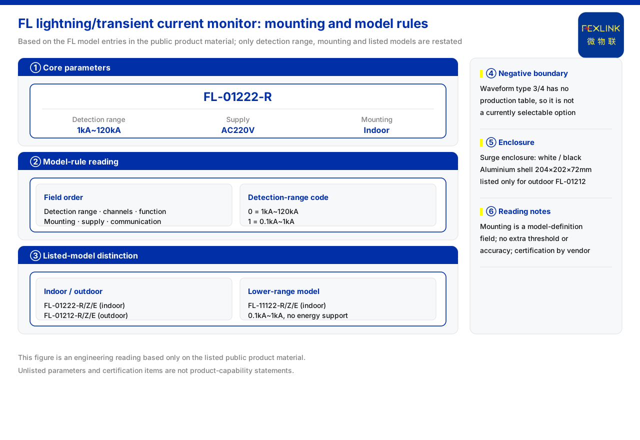
Direct answer
Selecting the FL lightning current/transient current monitor (FL-01222-R) essentially means treating the mounting method as a coded field just as important as detection range, function, and supply. The model rule given in the materials arranges detection range, channel count, function, mounting, and supply in order, with communication as a separate segment, which shows that mounting is part of the model definition rather than a mounting note added afterward. Indoor and outdoor models correspond to different structures and outlines, and under the same detection range each has its own model. The right approach is therefore to confirm first whether the site is an indoor or outdoor installation, then return to the listed production models and pick the one whose mounting matches; function directions such as the waveform setting, which have no production selection table, should not be treated as current options.
1. Mounting is written into the model rule
The materials record that the monitor's model rule orders the fields as detection range, channel count, function, mounting, and supply, with communication as a separate field. This order itself sets the sequence of selection judgment: first determine the current range to cover, then the channel count and function, and only then mounting and supply. Mounting is placed after detection range because it does not change the measurement principle but directly determines the enclosure, protection, and field installation conditions. In other words, one measurement capability can land on different mounting forms, and both must be confirmed together rather than looking only at range or only at outline.
2. Detection range decides the range setting
The model rule divides detection range into two settings: code 0 corresponds to 1 kA to 120 kA and code 1 corresponds to 0.1 kA to 1 kA. The former covers larger lightning currents, the latter smaller transient currents. When selecting, first answer what magnitude of transient event the site needs to record, then choose the detection-range code accordingly. Because the two settings correspond to different ranges, once the range is chosen wrongly the target event cannot be covered even if mounting is correct. The materials give no conversion across settings, so no inference should be made and only the listed settings should be chosen.
3. Function setting decides what is recorded
The function field of the model rule distinguishes recorded content into peak and peak plus energy. Among the listed production models, those supporting energy and those not supporting energy correspond to different detection ranges: the indoor and outdoor models covering 1 kA to 120 kA both support energy, while the indoor model covering 0.1 kA to 1 kA does not. Whether energy is recorded and the detection range therefore appear bound together in the current production models, and both should be checked together rather than treated as independent options.
4. Physical differences between indoor and outdoor models
The materials note that the outline differs by mounting: one is a lightning-protection monitoring enclosure available in white and black, and the other is an aluminum enclosure measuring 204 × 202 × 72 mm, corresponding to the outdoor model. Indoor and outdoor models may both use AC supply and the same range, but their outlines and structures differ. Mounting is thus not only a label but lands on enclosure material, dimensions, and installation conditions. For an outdoor exposed environment, choose the outdoor model; for an indoor cabinet environment, choose the indoor model. Matching mounting to outline avoids selecting a structurally unsuitable model.
5. Communication options and the listed models
The model rule treats communication as a separate field, and the listed models offer R, Z, and E communication options. The communication option determines how the device connects to the back-end link, so it should be chosen after mounting is fixed and in light of the existing gateway and network conditions. In particular, the materials list the waveform-setting models as a direction with no production selection table, meaning the currently selectable mounting methods correspond only to the listed production models. Selection should use the listed models as the boundary and not treat the non-production direction as an option.
6. A selection order matched by mounting
Taken together, the fields give a sequence matched by mounting: first, confirm whether the site is indoor or outdoor; second, determine the detection-range setting to cover; third, determine whether energy must be recorded; fourth, use the first three items to locate the model with the corresponding mounting among the listed models; fifth, choose the communication option in light of link conditions. This sequence places mounting in the middle rather than last because it is constrained by the first three items while deciding outline and structure. Both indoor and outdoor models use AC supply in the materials, so the supply field does not distinguish the current production models and need only be checked as it is.
7. Two cautions when matching mounting
First, do not conflate mounting with detection range. The materials show that indoor and outdoor models can both cover 1 kA to 120 kA, so mounting is not automatically determined by range; likewise, the models covering 0.1 kA to 1 kA also have their own mounting. Second, do not treat outline differences as packaging differences only. The aluminum enclosure corresponds to the outdoor model and the monitoring enclosure to the indoor model, and the difference in material and dimensions directly relates to field installation conditions. Checking mounting as an independent field, rather than inferring it from range, avoids mismatched selection.
8. Landing selection on field conditions
Bringing the field order back to the site explains why mounting is the pivot of selection. Field conditions usually appear first as an installation position: cabinet mounting in a distribution room, or a pole-top or open-air environment. Once the position is fixed, the two outline routes of the monitoring enclosure and the aluminum enclosure are largely settled, the latter corresponding to the outdoor model and the former to the indoor model. After the outline is confirmed, look back at detection range and function: for a larger lightning current with energy, the range falls on the setting covering 1 kA to 120 kA; for a smaller transient current, it falls on the 0.1 kA to 1 kA setting. Finally, choose the R, Z, or E communication option by field network conditions. Each field of the resulting model then corresponds to a field condition rather than an assembled guess. Because the materials give no conversion between mounting and protection rating, this step only matches listed models to site positions.
Scope and limitations
First, this article explains only the matching relationship between the monitor's selection and mounting, and the factual boundary is limited to the model rule, models, and outlines listed in the materials; it introduces no unlisted standard, parameter, or installation code.
Second, the materials give no quantitative relationship between mounting and protection rating, field wiring, or engineering acceptance; the matching sequence in the text is a general step induced from the listed fields and models and does not constitute an engineering calculation.
Third, the ranges, outline dimensions, and communication options mentioned are those already recorded in the materials; this article does not infer the specifications of unlisted models from them, nor does it infer monitoring effects.
Fourth, a specific project should be confirmed against field installation conditions and the listed production models; this article provides no selection conclusion or configuration list.
Fifth, the materials list the waveform-setting models (function 3/4) as having no production selection table for now, so the currently selectable mounting methods correspond only to the listed FL models; this article records that boundary without treating the non-production direction as an option.