 FEXLINK Research Institute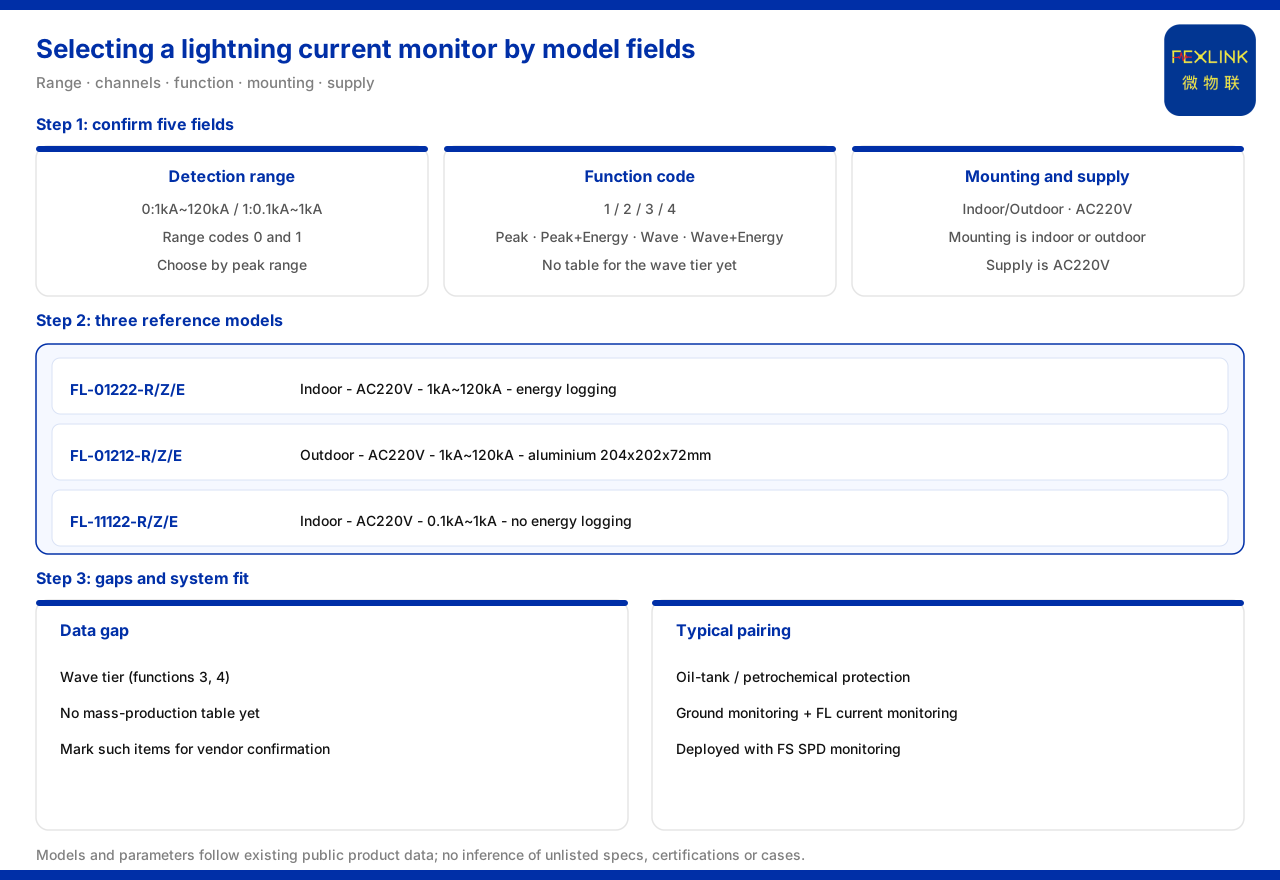
Direct answer
The most direct handle on selecting a lightning current / transient current monitor (FL) is its model rule. The product knowledge base records that an FL lightning current / transient current monitor model is built from five fields — detection range, channel count, function, installation method and power supply — plus a communication suffix, and selection should confirm each of these five fields one by one. Detection range code 0 stands for 1 kA to 120 kA and code 1 for 0.1 kA to 1 kA; function code 1 is peak, 2 is peak plus energy, 3 is waveform, and 4 is waveform plus energy. The parameter table of the product knowledge base lists three models for comparison: FL-01222-R/Z/E, indoor, AC220V, supporting energy recording; FL-01212-R/Z/E, outdoor, AC220V, supporting energy recording, with an aluminium housing of 204×202×72 mm; and FL-11122-R/Z/E, indoor, AC220V, with a peak range of 0.1 kA to 1 kA and an empty energy-recording cell. One reminder: appendix C of the product knowledge base lists a known information gap noting that waveform models (function 3 and 4) have no mass-production selection table yet, so items involving the waveform function should be marked as pending confirmation by the manufacturer.
1. Break the model into its five fields
The product knowledge base records that the FL model rule is FL plus detection range, channel count, function, installation method and power supply, followed by a communication suffix. This means a complete model carries five kinds of information at once: range, channel count, recording function, installation environment and power supply, closed by a communication suffix. In selection, skipping the fields to look only at the suffix easily ignores differences in installation method or supply conditions. The right way is to confirm field by field: fix the detection range, then the channel count, then the function, then the installation method and supply, and finally the communication. Once the five parts are separated, the model is no longer a string hard to tell apart but a checklist that can be confirmed item by item.
2. Detection range: two range levels
Detection range is the leading field. The product knowledge base records that detection range code 0 corresponds to 1 kA to 120 kA and code 1 to 0.1 kA to 1 kA. The two spans differ: one faces a larger lightning-current magnitude, the other a smaller transient-current magnitude. In selection, first estimate the current magnitude expected on the monitored circuit and choose one of the two range levels. The range is the boundary of recording capability, and a wrong range puts the record outside the effective interval, so this step should be fixed before function and installation. Note that the two range levels correspond to different recording targets: the high-current level faces high-amplitude currents such as a direct lightning strike, and the low-current level faces low-amplitude transients such as induced lightning or switching overvoltage. If a site has both large and small amplitudes, the emphasis of the range level should decide the choice rather than asking one monitor to cover both.
3. Function: four combinations of peak, energy and waveform
The function field decides which quantities are recorded. The product knowledge base records that function code 1 is peak, 2 is peak plus energy, 3 is waveform, and 4 is waveform plus energy, forming four combinations. If only the current peak is needed, take code 1; if energy must also be recorded, take code 2; if the waveform must be recorded, take code 3; if both waveform and energy are wanted, take code 4. From fewer to more, the corresponding recording dimensions increase step by step. Note that the materials also state the compatibility between energy recording and the low-current level, and the selection status of the waveform level, which are taken up below; in selection, the function code alone is not enough.
4. Three models compared: installation and range
The parameter table of the product knowledge base gives three models that can be compared directly. FL-01222-R/Z/E is indoor, AC220V, with a peak range of 1 kA to 120 kA and supporting energy recording. FL-01212-R/Z/E is outdoor, AC220V, with a peak range of 1 kA to 120 kA, also supporting energy recording, with an aluminium housing of 204×202×72 mm. FL-11122-R/Z/E is indoor, AC220V, with a peak range of 0.1 kA to 1 kA and an empty energy-recording cell. The three set each other off in installation environment and range: outdoor installation points to FL-01212, the small 0.1 kA to 1 kA range points to FL-11122, and the indoor high-current level points to FL-01222. All three list the communication suffixes R, Z and E, showing that networking method is selectable, while installation environment and range are the main fields that distinguish the models.
5. Energy recording and the low-current level do not coexist
One easily overlooked comparison is that energy recording is not available at every level. The parameter table of the product knowledge base shows that among the FL lightning current / transient current monitors, FL-01222 and FL-01212 support energy recording while the energy-recording cell of FL-11122 is empty. This means the low-current level and the energy-recording function do not coexist: once the small 0.1 kA to 1 kA range is chosen, energy recording cannot be required at the same time. If both a small range and energy recording are needed, one should recognise that the listed models cannot satisfy both and return to weighing function against range, rather than assuming all levels are alike.
6. The known gap at the waveform level
Function 3 and function 4 both involve the waveform. Item 3 of the known information gaps in appendix C of the product knowledge base notes that waveform FL models (function 3 and 4) have no mass-production selection table yet. Items involving the waveform function in a technical confirmation list should therefore be marked as pending confirmation by the manufacturer and not selected outright. The meaning of this gap is that waveform recording has a place in the model rule, but the materials do not yet give a mass-production model that can be selected directly. When a project meets a waveform need, it should first confirm with the manufacturer rather than deriving a waveform model that does not exist from the present parameter table.
7. Its supporting role in line-monitoring scenarios
A lightning current / transient current monitor is not used in isolation. In the scenario mapping of the product knowledge base, oil-tank-farm and petrochemical lightning-protection and explosion-proof recommends explosion-proof grounding resistance monitoring, FL lightning current monitoring and FS surge protective device monitoring deployed together. This shows that on the lightning-current side, FL forms a monitoring chain with grounding resistance monitoring and surge protective device monitoring: grounding looks at the earth-grid state, FL looks at lightning current and transient current, and surge protective device monitoring looks at the protective device state. In this combination, FL provides the record of lightning current and transient current and, together with the other two, supports the state judgment of a lightning-protection and explosion-proof location. If a site belongs to such a location, it should be considered as this combination rather than a single monitor.
Scope and limitations
First, this article only restates what the product knowledge base lists; its factual boundary is limited to the model rule of the FL lightning current / transient current monitor, its detection range and function codes, the three models in the parameter table, and the known gaps of appendix C, and it introduces no unlisted parameter, certification or case.
Second, the five-field composition of the model, detection range codes 0 and 1, function codes 1 to 4, the installation environment, supply, peak range and energy-recording state of the lightning current / transient current monitors FL-01222-R/Z/E, FL-01212-R/Z/E and FL-11122-R/Z/E, and the aluminium housing dimensions of the lightning current monitor FL-01212, are all quoted on the terms listed in the product knowledge base. The waveform level (function 3 and 4) having no mass-production selection table yet is a known information gap of appendix C, and this article only uses it to note that the related items should be marked as pending manufacturer confirmation, without inferring other unlisted models from it.
Third, the supporting combination of the oil-tank-farm and petrochemical lightning-protection and explosion-proof scenario and the FS surge protective device monitor are quoted on the terms listed in the product knowledge base. This article only explains the model fields and selection comparison of the lightning current / transient current monitor; it provides no specific engineering selection, configuration or range calculation, and the related conclusions must be verified against the on-site lightning-protection zones and circuit conditions, subject to the latest product materials and the project scheme.