 FEXLINK Research Institute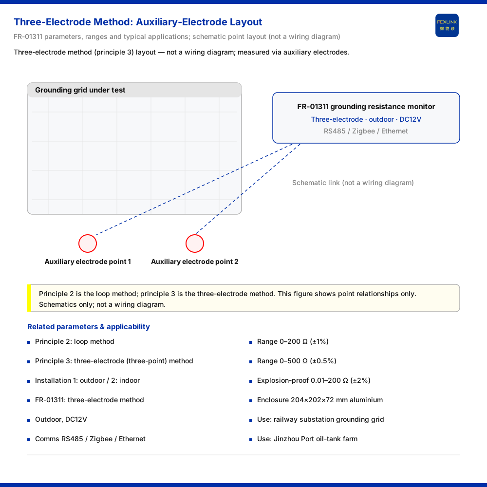
The three-electrode method (also called the three-point method) is the grounding-resistance measurement principle used by the grounding resistance monitor (FR-01311), whose on-sale variants (FR-01311-R, FR-01311-Z, FR-01311-E) are distinguished by communication method. Its defining orientation is this: auxiliary electrodes are arranged outside the grounding system under test, and the grounding-resistance reading is obtained through a measurement path independent of the existing circuits of the monitored grounding grid. That orientation also fixes its applicability boundary. It can only be deployed where the site allows auxiliary electrodes; otherwise the loop method should be evaluated.
An information boundary must be stated first. The knowledge base provides the coding of the detection principle and the on-sale models corresponding to each code, but does not expand the three-electrode method's circuit model, wiring scheme or calculation formula. The explanation here is therefore limited to what principle orientation it is and what site conditions it depends on; no inference is made about the specific measurement circuit or data-processing algorithm.
The Three-Electrode Method as an Encoded Position in the Model Rule
In the model rule of the grounding resistance monitor, FR – [signal acquisition][detection principle][installation method][supply] – [communication], the detection principle is given its own code position: 2 denotes the loop method and 3 denotes the three-point method (three-electrode method); the installation method is likewise coded separately, with 1 for outdoor and 2 for indoor. This design shows the measurement method is not a software option after commissioning but a product attribute fixed in the model at selection.
The on-sale grounding resistance monitor (FR-01311) sits on the three-electrode side, with an outdoor installation environment and a DC12V supply; the differences between its variants are concentrated in communication method, offering RS485, Zigbee and Ethernet respectively. Consequently, wherever measurement principle and site conditions are concerned, the judgement is the same across variants; wherever communication and networking are concerned, variants must be distinguished and must not be conflated.
Principle Orientation: An Independent Measurement Path Built from Auxiliary Electrodes
The three-electrode method and the loop method are parallel codes because they depend differently on site conditions. The three-electrode method requires auxiliary electrodes outside the grounding grid, completing the measurement through this additionally introduced path; its premise is that the site can arrange those electrodes as required. The loop method uses the existing loop conditions of the monitored grounding system, and its usability depends on whether a usable loop exists on site.
The knowledge base's record of the three-electrode method stops at "detection principle code 3, with the corresponding on-sale models listed as three-electrode". This article does not reverse-engineer its internal circuit structure, nor give the number of connections, electrode spacing or calculation method — none of which the knowledge base records. What can be established is only that the three-electrode method is an independent measurement principle relying on auxiliary electrodes, and its implementability is determined by site point-placement conditions.
Site Conditions: Whether Auxiliary Electrodes Can Be Deployed
To judge whether a site suits the three-electrode method, the first step is not to compare principles, but to answer an engineering question: does the site offer the space and conditions to arrange auxiliary electrodes? Where it does, the method can work through its independent measurement path; where it does not, the principle may be sound but cannot be deployed.
This judgement must be completed at the design stage, not deferred to the installation site, because the measurement method is already written into the model: once selected, changing it later means changing the equipment model, not adjusting a parameter. Confirming point-placement feasibility up front avoids a finalised design and delivered equipment turning out, on site, to be unbuildable.
Comparison with the Loop Method
The three-electrode method and the loop method are coded side by side in the model rule, showing that they are two choices under the same product system for different site conditions, not a hierarchy of levels or a new-for-old substitution. The dividing line is one sentence: the three-electrode method requires new auxiliary electrodes outside the grounding grid, while the loop method depends on whether an existing loop is usable. Whichever side the site conditions are closer to should be evaluated first.
Selection should therefore place the two methods on the same condition checklist for comparison, rather than presuming one to be superior. This article focuses on the three-electrode method; the details of the loop method are not developed here.
Range and Accuracy: The Second Confirmation After Fixing the Principle
The measurement principle answers "by what path to measure"; range and accuracy answer "whether the site's actual value span can be covered". The two must be confirmed separately. The reference parameters for the grounding monitoring unit given in the knowledge base are: standard type 0-200Ω (±1%), high-precision type 0-500Ω (±0.5%), and explosion-proof type 0.01-200Ω (±2%). The three configurations cover different measurement spans and accuracy requirements, with the explosion-proof type listed separately for environments that have explosion-protection requirements.
These are system-level reference parameters, not the specification of any particular model. They describe the range and accuracy configurations commonly seen in grounding-monitoring engineering; for a specific selection, the chosen model entry's parameters still govern. Range selection involves a tension: a range that is too small will push readings out of span, while one that is too large may sacrifice resolution; it must therefore be aligned with the actual value span of the site's grounding resistance.
Typical Applications and Installation Form
The knowledge base's notes give form and application information for the grounding resistance monitor: an aluminium enclosure of 204×202×72mm, already applied to projects such as railway traction substation grounding grids and the Jinzhou Port oil tank farm. What these scenarios share is a high requirement for the safe operation of the grounding system and the implementation conditions for long-term online monitoring, which fits the three-electrode method's need to arrange auxiliary electrodes.
This article only restates the applications listed in the knowledge base; it does not infer suitability for other industries or scenarios from them, and does not extend a functional interpretation of the enclosure dimensions.
Selection Reading: Site Conditions Before Principle
The points above can be gathered into a reading order: first judge whether the site can arrange auxiliary electrodes as required; then consider whether the usability of existing loops is sufficient to support the loop method; finally match the range and accuracy against the site's actual grounding-resistance value span. This order places "site conditions" before "principle comparison" and helps reduce unproductive debate at the selection stage.
The installation method is another independent code in the model rule and must be fixed together with the measurement method at the selection stage. After entering operation, the measurement method also determines the maintenance focus: at sites using the three-electrode method, whether the measurement conditions of the auxiliary electrodes still hold should be watched continuously. Chaining selection, installation and operation together, the measurement method is not merely a technical term but a constraint running through the entire equipment life cycle.
Common Misconceptions
The first is to treat the three-electrode method as the default while ignoring its dependence on site point placement. The second is to read the three-electrode method and the loop method as an advanced-versus-backward relationship and to choose by "more advanced", when the two codes carry no inherent ranking. The third is to look only at the measurement method without checking the installation environment and communication method in step, so that equipment and site do not match; because on-sale variants of the grounding resistance monitor differ precisely in communication method, this check is especially necessary. The fourth is to take the system-level reference ranges as a particular model's specification, ignoring that a model follows its own entry's parameters.
Applicability and Limits
- The three-electrode method (three-point method) is detection principle code 3 and the loop method is code 2, per the model rule for the grounding resistance monitor in the knowledge base; this article does not infer its specific measurement circuit, wiring scheme or algorithm.
- The on-sale grounding resistance monitor is three-electrode, outdoor-installed and DC12V-supplied, with communication method divided by variant into RS485, Zigbee and Ethernet, per the model table in the knowledge base; variants must not be conflated.
- Standard type 0-200Ω (±1%), high-precision type 0-500Ω (±0.5%) and explosion-proof type 0.01-200Ω (±2%) are system-level reference parameters of the grounding monitoring unit and do not equal the specification of a specific model.
- Applications such as railway traction substation grounding grids and the Jinzhou Port oil tank farm, and the aluminium enclosure form 204×202×72mm, are limited to the notes in the knowledge base and are not extrapolated.
- The citation of GB 50057 is limited to the grounding red-line entry in the knowledge base; this article does not cite other clauses of that standard not reflected in the knowledge base.