 FEXLINK Research Institute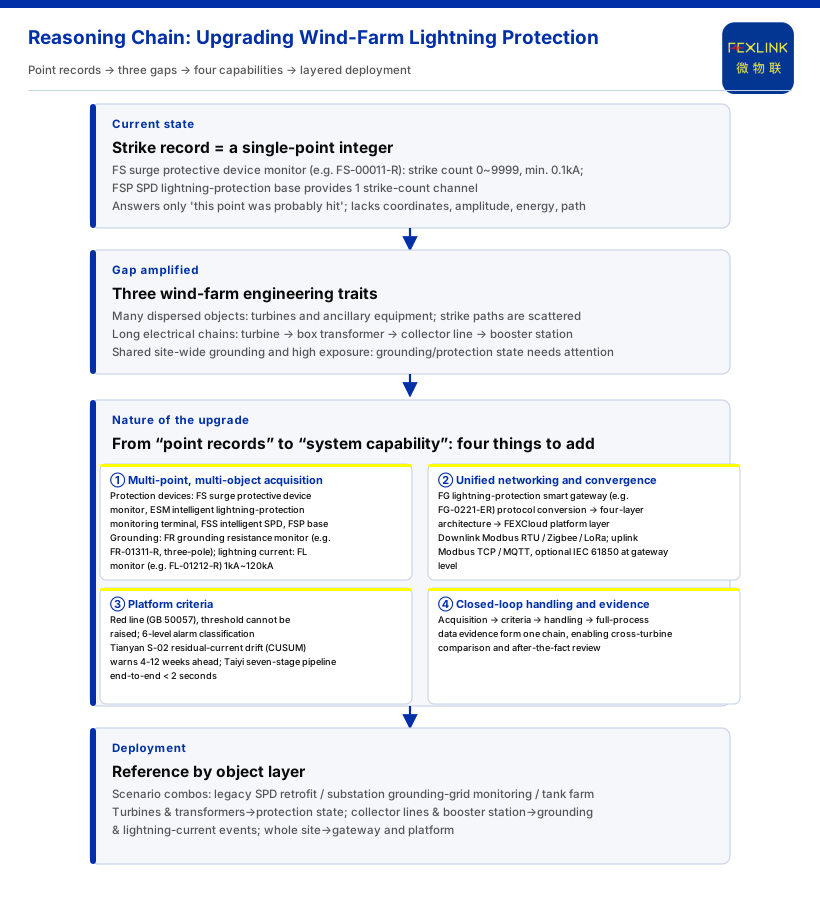
A wind farm already keeps "strike records": a counter increments, or a strike is logged. That answers "this point was probably hit", not which turbines a storm struck, which paths it entered, which protective devices absorbed stress, or whether the grounding and protection chain is intact. A wind farm is not a single-point device: turbines are dispersed, box-type transformers and collector lines form a network, plus a booster station and site-wide shared grounding. An isolated record cannot relate strike points, form cross-position criteria, or close a loop of response and evidence. An intelligent lightning-protection system fills exactly this layer from "point record" to "system capability".
1. What a "Strike Record" Answers, and Where It Falls Short
Records have value. The knowledge base documents the FS surge protective device monitor (e.g. FS-00011-R) with a strike-count range of 0~9999 and a minimum trigger of 0.1kA; it can indicate a lightning-current event at a point without waiting for device damage. The FSP SPD lightning-protection base also provides 1 strike-count channel. But as a record it is a point-based integer of "count": no cross-point coordinate, no amplitude, energy or path. At dozens or hundreds of turbine positions, the gap between "this point was hit a few times" and "the storm's overall impact" is not data volume but the level of the question.
2. Why a Wind Farm Amplifies the Record Gap
First, many dispersed objects. Many turbine positions and supporting electrical equipment scatter strike points and entry paths; recording one point cannot assemble a distributed phenomenon into a whole.
Second, long electrical chains. Turbines feed through box-type transformers and collector lines into a booster station; energy and interference may cross devices and voltage levels, and protection acts at several stages; without cross-stage links, the source is hard to identify.
Third, site-wide shared grounding and external exposure. Grounding is the site-wide safety floor, and open-terrain wind farms face pronounced lightning exposure, making grounding and protection changes worth continuous attention.
3. The Essence of the Upgrade: Four Things from "Point Record" to "System Capability"
The upgrade is not replacing records or adding counters, but letting dispersed records converge into system capability. The knowledge base's intelligent lightning-protection line (FS/ESM/FR/FL/FG) provides verifiable support.
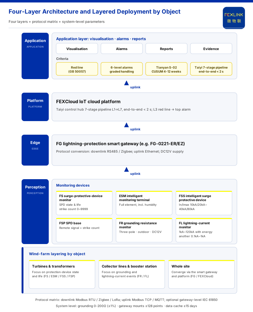
First, multi-point, multi-object acquisition. On the protective-device side, the FS surge protective device monitor covers remote signalling, breaker status, grounding status, strike count, leakage current, temperature, voltage and life prediction, with leakage 50.0~1200.0μA, voltage 0~400.0V, temperature -20~100℃, strike count 0~9999 and life prediction 0~100%; the ESM intelligent lightning-protection monitoring terminal is a full-element terminal including humidity; the FSS intelligent surge protective device offers In/Imax from 10kA/20kA to 40kA/80kA and Up 1.5kV~2.2kV. On the grounding side, the FR grounding resistance monitor (e.g. FR-01311-R) uses the three-electrode method with DC12V supply and outdoor installation, supporting RS485/Zigbee/Ethernet. On the lightning-current side, among the FL lightning current / transient current monitors (e.g. FL-01212-R), indoor and outdoor versions peak at 1kA~120kA with energy monitoring, another at 0.1kA~1kA. Underlying this is the core sensor technology in the knowledge base, such as the board-mounted shaped Rogowski coil capturing 1μs-class abnormal currents.
Second, unified networking and convergence. The knowledge base defines a four-layer architecture of perception, edge, platform and application; the FG lightning-protection smart gateway (e.g. FG-0221-ER) is protocol-conversion type with downstream RS485 or Zigbee, upstream Ethernet and DC12V supply, converging their readings into one link. The protocol matrix supports downstream Modbus RTU, Zigbee and LoRa, and upstream Modbus TCP / MQTT plus gateway-level optional IEC 61850. System-level reference parameters include grounding monitoring units covering 0-200Ω (standard type, ±1%), and a smart gateway hosting ≥128 points with ≥15 days of data cache.
Third, platform criteria. Turning data into action needs a non-bypassable floor and grading. The knowledge base lists "abnormal open circuit of grounding resistance" as the red line (per GB 50057), which no one can raise; its six-level alarm system grades urgency as Normal (85-100), Watch (70-84), YJ1 (55-69), YJ2 (40-54), BJ1 (20-39, handle within 48 hours), BJ2 (0-19, immediate shutdown). At trend level, the Tianyan engine's S-02 residual-current trend drift (CUSUM) model detects weak mean drift while leakage is still safe, warning 4-12 weeks ahead. On the platform side, the Taiyi intelligent-control hub's seven-stage pipeline runs end to end in under 2 seconds, where an L3 red-line trigger directly emits the highest-level alarm; the knowledge base also lists new-energy stations among applicable industries.
Fourth, closed-loop response and evidence. A "record" stops at "it happened"; a system strings acquisition, criteria, response and whole-process evidence into one chain, enabling cross-position comparison. Note: the knowledge base gives only recommended scenario-to-product mappings, not sampling and reporting frequency, offline cache and backfill strategy, alarm-ticket grading rules or evidence format, and this article does not infer them.
4. Where This System Lands in Engineering
The scenario cross-reference gives modular combinations: surge-protector status monitoring (retrofit of existing SPDs) maps to the FS surge protective device monitor / ESM full-element SPD monitoring / FSP base; on-line grounding-grid monitoring for substations and traction substations maps to the FR grounding resistance monitor (1 set per point) + FG gateway + FEXCloud; oil-tank-area / petrochemical scenarios map to explosion-proof grounding resistance monitoring, FL lightning-current monitoring and FS surge-protector monitoring. For a wind farm these are references layered by object — turbine positions and box transformers on protective-device status, collector lines and the booster station on grounding and lightning-current events, converging through the gateway and platform. But the knowledge base has no wind-farm-specific scenario row; this article also gives no retrofit procedures, construction sequence or bill-of-quantity figures.
5. Boundaries: What This Article Does Not Claim
Second, the quantitative indicators in the knowledge base (e.g. electrical-hazard identification 95%+, alarm compression 80%, 4-12 weeks' warning lead, MTTR reduced 60%, energy-saving potential 8-20%) are vendor self-reports; cite them only as vendor capability claims, never as effect guarantees or procurement grounds.
Third, the knowledge base lists no wind-farm-specific model, parameter or certification, and no generation loss, payback period, diagnostic effect or customer case; this article asserts none, nor does it give sampling and reporting frequency, offline cache and backfill strategy, alarm-ticket grading rules or evidence format.
Fourth, this article cites only standard names the knowledge base lists — GB 50057, GB 13955, GB 16895 and others — without inferring clauses.
Fifth, this article covers the "count → event diagnosis" shift for the turbine blade; broader or cross-scenario topics belong to other articles and are not developed here. It answers only why wind-farm protection must upgrade, and the supporting capabilities, without repeating those landing points or reusing old drafts.
Conclusion
Wind-farm lightning protection must upgrade not because records are useless, but because a "point record" cannot match the system scale of a wind farm: many dispersed objects, long electrical chains and site-wide shared grounding mean isolated counts cannot answer "which turbine positions are affected, which path is taken, and whether the protection chain is intact". The essence is to converge records into system capability — the FS surge protective device monitor, ESM intelligent lightning-protection monitoring terminal, FSS intelligent surge protective device and FSP SPD lightning-protection base for device status and life; the FR grounding resistance monitor for grounding; the FL lightning current / transient current monitor for lightning-current events; convergence through the FG lightning-protection smart gateway with the four-layer architecture, protocol matrix and system-level parameters; the floor held by the red line and six-level alarms and warning moved earlier Tianyan S-02; and landing points from existing combinations. From record to system, the essence is upgrading "a point was hit" into "is site-wide lightning protection still effective, and what should be done".