 FEXLINK Research Institute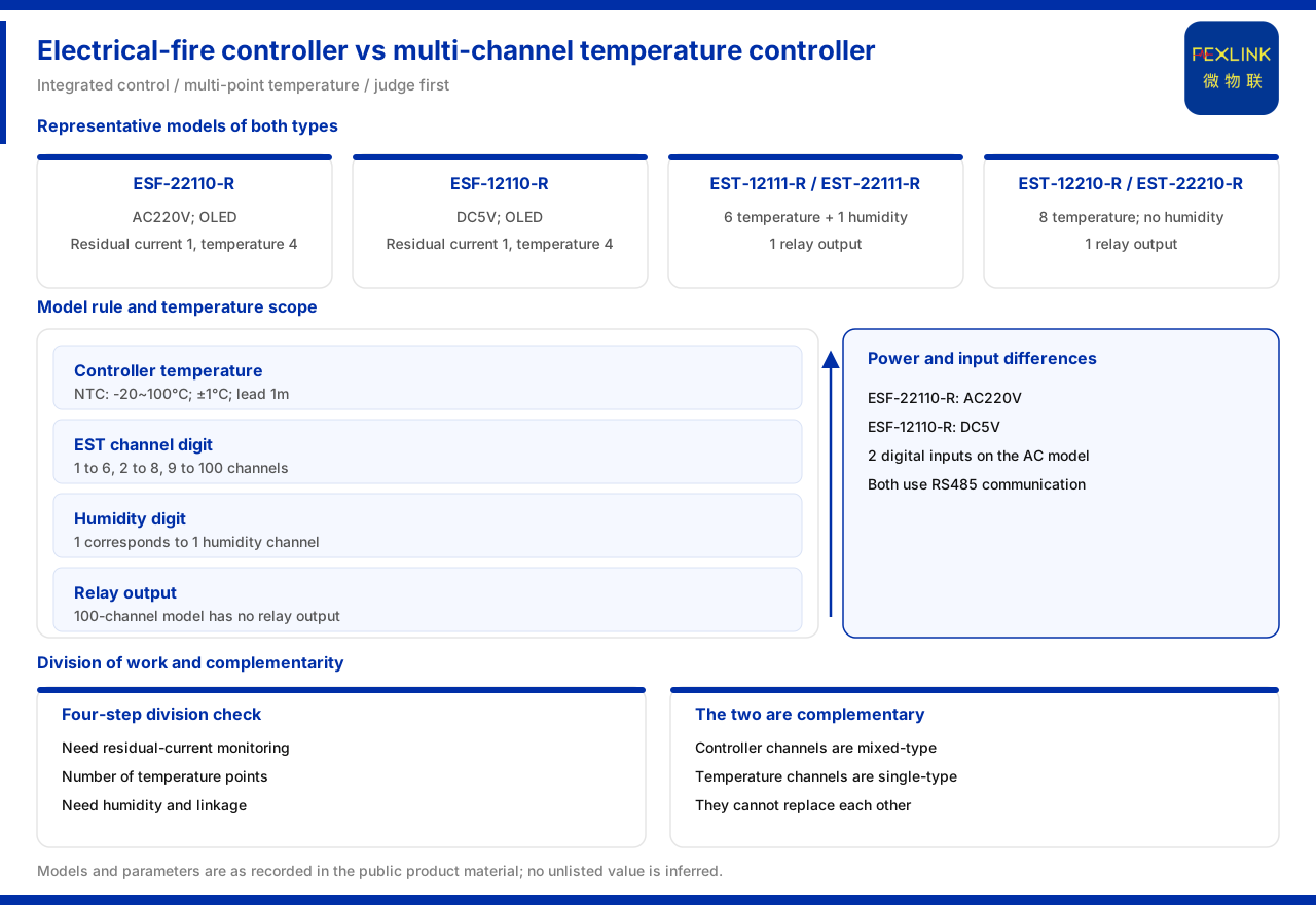
Electrical fire monitoring & control device versus multi-channel temperature controller: how exactly do they divide the work?
Direct answer: both device types involve temperature, but their positioning differs. The electrical fire monitoring & control device, besides temperature measurement, also carries residual current, digital inputs and relay outputs; it is an integrated control device aimed at electrical fire. The multi-channel temperature controller treats temperature as its main item and provides 6 or 8 temperature channels, with some models also offering 1 humidity channel. Taking specific models as examples, the electrical fire controller ESF-22110-R provides 1 residual-current path, 4 temperature paths, 2 digital inputs, 1 relay output and RS485, powered by AC 220 V; the temperature controller EST-12111-R provides 6 temperature paths plus 1 humidity path. In selection, first judge whether the site needs "one integrated control device" or "multi-point temperature acquisition", and the division of labour becomes clear.
The two supply variants of the electrical fire controller
The material lists two representative models of the electrical fire controller. ESF-22110-R is powered by AC 220 V and has an OLED display; its channels include 1 residual-current path, 4 temperature paths, 2 digital inputs and 1 relay output, with RS485 communication. ESF-12110-R is powered by DC 5 V and likewise has an OLED display; its channels include 1 residual-current path, 4 temperature paths and 1 relay output, with RS485 communication.
The difference between the two models lies first in the supply system: one faces an AC 220 V site and the other a DC 5 V site. It lies second in the input configuration: ESF-22110-R explicitly lists 2 digital inputs, whereas no digital-input item appears in the material formulation for ESF-12110-R.
Temperature-measurement parameters of the electrical fire controller
The material gives the key temperature-measurement parameters of this series: an NTC measurement range of -20 to 100°C, an accuracy of ±1°C, and an external cable length of 1 m. Four temperature paths mean four measuring points can be covered, suitable for placement at key connections in a distribution cabinet or on a line.
The 1 m external cable length is an easily overlooked constraint. It limits the reachable distance from the sensor body to the measuring point; if the field point is far from the mounting position, the extension method must be confirmed at the scheme stage, and the freedom of layout must not be inferred directly from the 4 temperature paths. The range of -20 to 100°C and the accuracy of ±1°C are the basic formulation for judging whether the field conditions are suitable.
Two temperature configurations of the multi-channel temperature controller
The multi-channel temperature controller is divided into two classes by temperature-path count. EST-12111-R and EST-22111-R have 6 temperature paths plus 1 humidity path and also carry 1 relay output; EST-12210-R and EST-22210-R have 8 temperature paths and do not include a humidity channel. The difference between the two classes is both the path count and the presence of humidity.
The 6-path-plus-humidity configuration suits sites that care about both temperature and ambient humidity; the 8-path configuration concentrates the channels on temperature measuring points. Selection can first determine whether a humidity parameter is needed and then decide the path count. If the site cares only about temperature distribution, the 8-path model offers more points; if humidity is also a concern, the 6-path-plus-humidity combination fits better.
How to read the model rule
The material gives the model coding rule of this series, in which path digit 1 corresponds to 6 paths, 2 to 8 paths and 9 to 100 paths; humidity digit 1 corresponds to 1 humidity path. With this rule, reading a model number quickly reveals the channel scale.
For example, when path digit 1 and humidity digit 1 appear together, that corresponds to 6 temperature paths plus 1 humidity path; path digit 2 corresponds to 8 temperature paths. The value of the rule is that it avoids memorising models one by one: parsing by digit allows quick cross-checking beyond the selection table. It should be emphasised that the rule is a method of reading the model, and whether a particular model actually has a given channel must still be based on the model table.
Differences in relay output
The material states that the representative models of the 6-path and 8-path temperature types both carry 1 relay output, while the 100-path type does not carry relay output. This difference is critical for linkage design: if the device is required to drive an external circuit directly when the temperature is abnormal, a model with relay output should be chosen; if only data upload is needed and the upper platform makes the decision, the relay is not essential.
Looking at relay output together with the path count gives a clear trade-off: the 6-path and 8-path types balance channels and linkage, while the 100-path type concentrates its capability on temperature acquisition from a large number of points. Selection should first clarify whether the control responsibility rests with the device side or the platform side, and then decide whether relay output is required.
General specifications and environmental adaptability
The material gives the general parameters of this series: power consumption no more than 2 W, operating temperature -20 to 60°C, humidity below 95%, dimensions 36 × 110 × 69 mm, protection rating IP20, and 35 mm rail mounting. These parameters determine what kind of cabinet and environment the device can be placed in.
IP20 and 35 mm rail mounting show that it faces in-cabinet installation and is not suitable for direct exposure to open environments with high humidity or heavy dust. Power consumption of no more than 2 W means a small heat burden during long operation.
Can the two device types replace each other?
A common idea is that since both can measure temperature, perhaps only one type is needed. According to the material formulation, this substitution does not hold. The electrical fire controller has a fixed 4 temperature paths and also carries residual current and digital inputs; the multi-channel temperature controller has more temperature paths but does not include residual-current monitoring. Replacing the former with the latter would lose the key quantity of residual current; replacing the latter with the former would usually leave too few temperature points. The two device types are therefore closer to a complementary relationship than an either-or choice.
This judgement also explains the difference in model design: the channels of the electrical fire controller are "mixed", organised around several quantities related to fire; the channels of the multi-channel temperature controller are "single-type", expanded around temperature as the main item.
Four steps for the division of labour
First, see whether residual-current monitoring is needed. If so, the electrical fire controller should be considered first, because the temperature controller does not include that channel.
Second, see how many temperature points are needed. A small number of points can use the controller with 4 temperature paths, while many points call for the 6-path or 8-path temperature controller.
Third, see whether humidity is needed. When humidity is needed, choose a model with the humidity digit; when not, use the 8-path temperature type.
Fourth, see whether device-side linkage is needed. When relay output is required, avoid the 100-path type and choose a model with relay output.
Material boundaries and practical notes
First, the material gives no installation-position specification for temperature points; point layout must be designed according to the site structure.
Second, the material gives no range details for the residual-current channel; if a project needs a definite range, it should be checked separately.
Third, the material gives no linkage configuration rule for the two device types; how the controller and the temperature controller cooperate must be defined on the scheme side.
Fourth, the material gives no permitted method of extending the sensor; scenarios beyond the 1 m external cable length require separate confirmation.
Summary
The division of labour between the electrical fire monitoring & control device and the multi-channel temperature controller can be summarised as follows: the former provides residual current, digital inputs and relay outputs in addition to temperature, with representative models such as ESF-22110-R and ESF-12110-R, NTC measurement of -20 to 100°C with an accuracy of ±1°C and a 1 m external cable length; the latter takes temperature as its main item, in 6-path or 8-path configurations, with representative models such as EST-12111-R and EST-12210-R, a model rule in which path digit 1 corresponds to 6 paths, 2 to 8 paths and 9 to 100 paths, humidity digit 1 to 1 humidity path, and the 6-path and 8-path types carrying 1 relay output while the 100-path type does not.
Judge first whether "integrated control" or "multi-point temperature measurement" is needed, then check supply, channels and linkage, and the two device types will not be mixed up in selection.