 FEXLINK Research Institute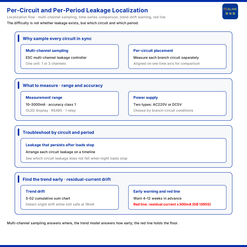
Direct answer
For a branch circuit whose leakage is normal in the daytime and exceeds the limit at night, the difficulty is not whether there is leakage but which circuit and which time window. The capability combination the product knowledge base gives is this: use the multi-channel leakage-current monitoring and control device (ESC-22310-R) to acquire synchronously by branch circuit, with one unit supporting one channel or three channels of monitoring and a measurement range of 10 mA to 3000 mA at accuracy class 1; then combine the time series to recognise the persistent leakage that remains after the night-time load has stopped. With the residual-current trend drift model of the Tianyan engine, a weak drift can be detected while leakage is still within the safe range, giving a warning 4 to 12 weeks ahead. This article explains the method of locating leakage by circuit and by time window and marks the material boundary.
1. Why synchronous acquisition by circuit
The traditional approach is often to measure in rotation on the main circuit, which captures only an overall leakage value. The problem is that a normal overall value does not mean every branch is normal; an anomaly in one branch can be masked by the other branches. The ESC-22111-R multi-channel leakage-current monitoring and control device of the product knowledge base supports one channel or three channels of leakage monitoring per unit; the ESC-22311-R belongs to the same device family, while the ESC-12111-R and the DC 5 V ESC-12311-R complete the model set.
Placing points by branch circuit measures the leakage of each circuit rather than a merged total. When a circuit rises in a particular time window, the data shows directly which circuit it is, instead of waiting until the main circuit also exceeds the limit. Synchronous acquisition has a further meaning: data from different circuits is aligned on the same time axis, so that cross-comparison and longitudinal comparison both hold.
2. What to measure: measurement range and accuracy
Leakage has to be spoken of in numbers. The leakage measurement range the product knowledge base gives is 10 mA to 3000 mA at accuracy class 1. This range means leakage currents from very small to large are covered, and class 1 accuracy ensures the measured value can be used for comparative judgement.
The device uses an OLED display, communicates over RS485, and has one relay output. The relay output allows local interlocking, so that not all handling has to return to the platform side. For operation and maintenance, local display and local output make field verification much easier. The parameters are few, but each corresponds to a concrete field action: reading the data, wiring, and interlocking.
3. How to place points: power supply and branch-circuit adaptation
Point placement must consider the distribution environment. The product knowledge base states that the supply of the multi-channel leakage-current monitoring and control device falls into two classes: ESC-22310-R and ESC-22111/22311-R are AC 220 V; ESC-12111/12311-R are DC 5 V. Choosing the supply according to the distribution conditions of the branch circuit makes placement easier.
This point is often overlooked, yet it strongly affects whether point placement by circuit is possible. Under some cabinet-space or power take-off conditions, AC 220 V take-off is inconvenient, and the DC 5 V version is more suitable. The choice of supply makes multi-circuit point placement more feasible on site and leaves older distribution cabinets less constrained during retrofit.
4. Troubleshooting night-time exceedance: by circuit and by time window
Back to the core question: normal in the daytime, exceeding the limit at night. The product knowledge base does not directly give a causal conclusion for night-time exceedance, and the material boundary must be stated. However, since the device can acquire by circuit at the same time and with timestamps, troubleshooting has a method: arrange the leakage of each circuit by time and observe which circuit's leakage fails to fall after the night-time load has stopped.
Leakage that persists after the load stops is usually more suspect, because it cannot easily be explained by ongoing use. Comparing by circuit and by time window can break overall leakage down into which circuit and which time window, and so determine where to inspect first. What is given here is a troubleshooting approach; the specific causes still need to be confirmed by field testing. Its value is in narrowing the range, not replacing field testing.
5. Early trend detection: residual-current trend drift
Besides after-the-fact location, there is early detection. The S block of the Tianyan engine of the product knowledge base includes S-01 resistive leakage separation and S-02 residual-current trend drift, the latter using the cumulative sum control chart method. It can detect a weak mean drift while leakage is still within the safe range, for example 18 mA, and gives a warning 4 to 12 weeks ahead.
This corresponds exactly to gradual problems such as night-time exceedance. By the time a value crosses the threshold, it has usually accumulated for some time; the role of the trend drift model is to see the direction while the value is still safe. For finding persistent leakage trends along the time series, this is a usable path. In other words, multi-channel acquisition solves where, and the trend model solves how early.
6. Red-line and bottom line: the residual-current threshold
Beyond warning there is also a red-line. The Qianzhi engine of the product knowledge base groups the leakage sub-model into basic vital signs M01 to M05, adopts a time-series trend and performs a safety red-line pre-check. The safety red-line triggers when residual current is at or above 300 mA, under GB 13955. Once the red-line triggers, it no longer passes through weighted judgement.
The meaning of this line is to set a bottom line. Trend drift is responsible for early detection and the red-line for guarding the bottom line; together they neither let a gradual change slip through nor hesitate in a severe case. For duty personnel, the red-line is a clear action signal and does not require weighing scores.
7. From monitoring to scenario: the electrical hazard early-warning system
Placing these capabilities into scenarios makes the landing point clearer. In the typical application scenarios and selection comparison, the product knowledge base gives: for low-voltage distribution cabinet electrical fire warning, the electrical fire monitoring and control device (ESF-22110-R) with multi-channel leakage monitoring, a multi-channel temperature intelligent controller (EST-12111-R) and an IoT box; and for charging station or charging shed hazard warning, the electrical hazard early-warning system with leakage monitoring, temperature control and FEXCloud.
Among these, the electrical hazard early-warning system focuses on the charging scenario, covering both the two-wheel electric vehicle and new-energy vehicle charging systems, with a core of multi-parameter fusion intelligent algorithms, a charging-hazard thermal map, and dynamic data monitoring plus multi-dimensional analysis. The product knowledge base also notes that 90% of charging fires arise from undetected hazards. This indirectly shows that locating leakage clearly by circuit and by time window is precisely the key step in turning a hazard from undetected into handleable.
Scope and limitations
First, this article restates only what the product knowledge base lists; the factual boundary is limited to the records of the multi-channel leakage-current monitoring and control device, the leakage-related models of the Tianyan and Qianzhi engines, the electrical hazard early-warning system and the selection comparison.
Second, the one or three channels of monitoring, the 10 mA to 3000 mA range and class 1 accuracy, the OLED display, the RS485 communication and the one relay output of the multi-channel leakage-current monitoring and control device, as well as the AC 220 V or DC 5 V supply of each model, are cited as listed in the product knowledge base.
Third, the cumulative sum control chart method of S-01 resistive leakage separation and S-02 residual-current trend drift, the 18 mA case and the 4 to 12 weeks advance warning are cited as listed in the product knowledge base; this article does not present that warning as a guarantee for a specific project.
Fourth, the safety red-line of residual current at or above 300 mA and its GB 13955 basis are cited as listed in the product knowledge base; this article does not change their threshold or triggered consequences.
Fifth, the selection combinations for low-voltage distribution cabinets and charging scenarios, and the dual system, multi-parameter fusion, thermal map and 90% charging-fire implication of the electrical hazard early-warning system, are cited as listed in the product knowledge base.
Sixth, this article explains only the method of locating leakage by circuit and by time window and the material boundary, and does not provide specific engineering point-placement, setting or rectification schemes.