 FEXLINK Research Institute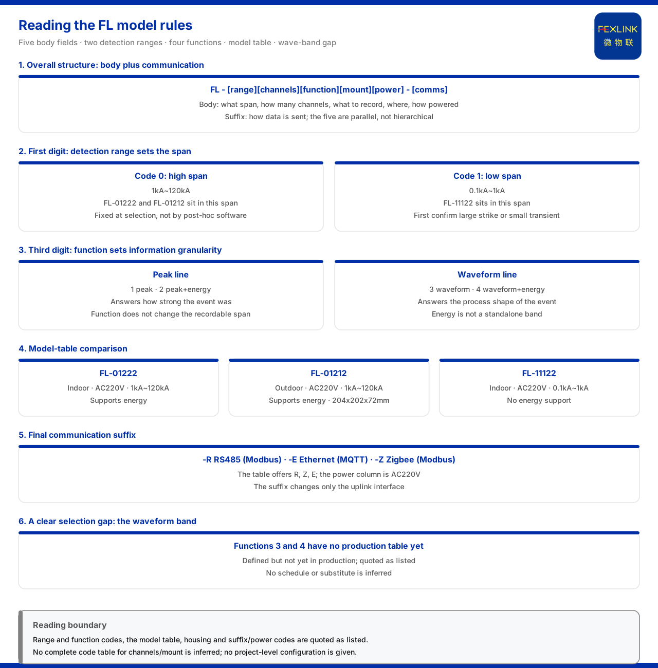
Direct answer
The model rule of the FL lightning current / transient current monitor (e.g. FL-01222-R) can be read as "a body segment of five field groups plus a communication suffix": the body segment is formed by detection range, channel count, function, installation method and power supply, with the communication method listed separately. The key is first to assign each position to its field, then to read the code values given by the product knowledge base. Among the current definitions, two positions matter most: the first, "detection range", determines the magnitude tier — 0 means 1kA to 120kA and 1 means 0.1kA to 1kA; the third, "function", determines the granularity of the recorded information — 1 is peak, 2 is peak plus energy, 3 is waveform and 4 is waveform plus energy. The remaining positions relate to installation environment and power supply and must be checked model by model against the model table. Split this rule apart and the model is no longer a string of digits but a set of checkable selection conditions.
1. Overall structure: a five-part body segment plus communication
The product knowledge base specifies that the model rule of the FL lightning current / transient current monitor is: the body segment is formed by detection range, channel count, function, installation method and power supply, with the communication method listed in the final segment. This writing is consistent with the general structure of lightning-protection products: the body segment answers "what magnitude is recorded, on how many channels, what is recorded, where it is installed and how it is powered", while the final segment answers "how the data is sent out". Reading any FL model should first split the rule into a "body segment" and a "communication segment", and then group the five body positions by field. Note that the five positions are parallel, not hierarchical: detection range describes magnitude and function describes granularity, and the two cannot substitute for each other.
2. First position: detection range determines magnitude
The product knowledge base gives the detection-range codes clearly: 0 means 1kA to 120kA, a high range; 1 means 0.1kA to 1kA, a low range. This position decides "what magnitude of lightning current or transient current is to be recorded", which is why it stands at the head of the model. In the model table, FL-01222 and FL-01212 fall in the 1kA to 120kA span, while FL-11122 falls in the 0.1kA to 1kA span. The range is thus not a parameter adjusted later in software but one fixed at the selection stage by the first position. In selection, confirming whether the site needs to record a larger lightning current event or a smaller transient current event fixes this position first.
3. Third position: the function position determines information granularity
The function position decides the information granularity included in the event record. The product knowledge base divides it into four tiers: 1 for peak, 2 for peak plus energy, 3 for waveform and 4 for waveform plus energy. These can be grouped into two main lines: the peak line answers "how strong this event was" and the waveform line answers "the process shape of this event"; energy does not stand as a tier on its own but is superimposed on the two lines. The function position therefore does not change the magnitude the instrument can record, only what information it can record. In the model table, FL-01222 and FL-01212 support energy while FL-11122 does not, corresponding to different function values. In selection, to reconstruct the process shape one should look to the waveform tier; if only strength information is needed, the peak tier suffices; and whether energy is needed is considered as a superposition on the relevant line.
4. Remaining positions and the model table
The values of the second body position "channel count", the fourth "installation method" and the fifth "power supply" must be checked against the model table. The FL model table of the product knowledge base lists three mass-produced models, with their installation environment, power supply, detection range and energy support as follows:
| Model | Detection range | Function (energy) | Installation environment | Power supply |
|:--|:--|:--|:--|:--|
| FL-01222 | 1kA~120kA | Supports energy | Indoor | AC220V |
| FL-01212 | 1kA~120kA | Supports energy | Outdoor | AC220V |
| FL-11122 | 0.1kA~1kA | Does not support energy | Indoor | AC220V |
As the table shows, all three are supplied at AC220V and differ in detection range, energy support and installation environment: the two high-range types support energy, the low-range type does not, and FL-01212 is the outdoor type while the other two are indoor. The "installation environment" column corresponds exactly to the field meaning of the "installation method" position in the body segment. When reading a model, therefore, one must not read only the digits but also check the installation environment and power supply against the model table, matching them to site conditions.
5. The final communication suffix
The final communication suffix decides how the data is sent out. The general suffix rule of the product knowledge base specifies: -R is RS485 (Modbus), -E is Ethernet (MQTT) and -Z is Zigbee (Modbus); supply-mode code 2 of lightning-protection products corresponds to AC220V. In the model table, the communication column of the FL types offers R, Z and E options and the supply column is AC220V, corresponding to the general rules above. This shows that the communication suffix does not change range or function, only the interface method of the uplink. In selection, the recording scheme can first be fixed by the body segment, and the suffix then chosen by on-site networking conditions; the two are decided separately.
6. A clear selection gap: the waveform tier
One gap explicitly recorded by the product knowledge base must be pointed out when reading this model rule. In item 3 of the known information gaps in its appendix, the product knowledge base states that the waveform-tier FL models (function values 3 and 4) have no mass-produced selection table for the time being. This means that although the function position defines a waveform tier and a waveform-plus-energy tier, currently these two tiers have no mass-produced model available. Where a waveform-recording objective is required, therefore, the corresponding model cannot be found directly in the model table; the tier can only be confirmed to exist in definition but to be absent in mass production. This gap is a known information gap self-stated by the product knowledge base; this article transcribes it and infers no subsequent schedule or alternative.
7. Reducing the reading to a checking order
Putting the above together, the reading of the FL model rule reduces to an order. First, read the first position to fix the detection range, high or low. Second, read the third position to fix the function — peak, peak plus energy, waveform or waveform plus energy; if it falls on the waveform tiers, note the gap that no mass-produced model exists yet. Third, return to the model table to check whether the installation environment and power supply match the site. Fourth, choose the communication method by the final suffix. By this order, the model rule answers "what this instrument records, up to what magnitude and where it is installed", not a vague "the larger the range the better". Aligning each position with the site conditions is the correct way to read an FL model.
Scope and limitations
First, this article restates only what the product knowledge base lists, with the factual boundary limited to the model rule of the FL lightning current / transient current monitor, the definitions of the detection-range and function codes, the model table, the housing, and the general suffix rule and supply-mode codes of lightning-protection products.
Second, detection-range code 0 meaning 1kA to 120kA and 1 meaning 0.1kA to 1kA, and function codes 1 to 4, are cited from the product knowledge base; this article infers no complete code table for the channel-count and installation-method fields, and the relevant values are subject to the model table.
Third, the installation environment, power supply, detection range and energy support of the lightning current monitor's FL-01222, FL-01212 and FL-11122, and the FL housing (lightning-protection monitoring housing in white / black, outdoor type aluminium 204×202×72mm), are cited from the product knowledge base.
Fourth, the gap that waveform-tier FL models have no mass-produced selection table comes from item 3 of the known information gaps in the product knowledge base appendix; this article transcribes it and infers no subsequent schedule or alternative.
Fifth, this article only explains how to read the FL model rule position by position and provides no specific project detection-range selection, function configuration or installation scheme; the relevant conclusions must be confirmed with the on-site lightning environment and the project solution.
Sixth, this article constitutes no commitment about the selection result or field behaviour of a specific project; actual conditions are subject to the latest product material and project solution.