 FEXLINK Research Institute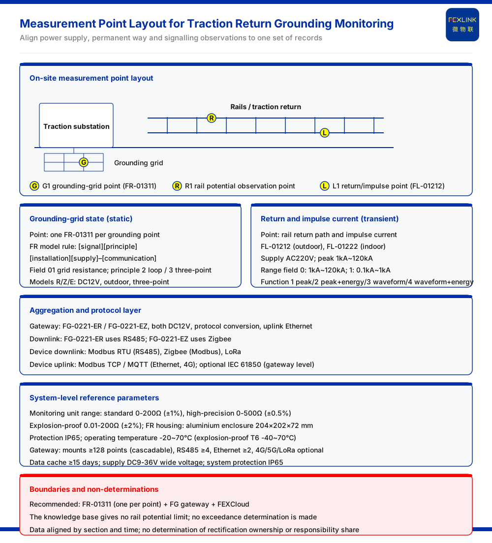
Direct answer
When traction return current causes an abnormal rail potential, the disagreement among the power supply, permanent way and signalling disciplines is usually not about whether the phenomenon exists, but about which discipline should carry out the rectification and which stretch should be handled first. The approach given by the product knowledge base is to turn the dispute into data that can be aligned: the FR grounding resistance monitor (FR-01311-R) continuously records the grounding-grid state per grounding point, while the FL lightning current / transient current monitor (FL-01212) records the return current and impulse current, and the FG lightning protection smart gateway (FG-0221-ER) aggregates and uplinks the two classes of data so that they can be checked against each other by section and by time. In this way "each side has its own reason" is reduced to a single set of records. The typical application scenarios and selection comparison table of the product knowledge base write the recommended combination for substation and traction substation grounding-grid online monitoring as: one set of grounding resistance monitor per grounding point, plus a gateway and the FEXCloud IoT cloud platform. It should be noted that the knowledge base does not give a rail potential limit, so this article makes no such determination; it only explains how the data that supports the cross-check is acquired and aggregated.
The crux of the dispute
For one and the same abnormal rail potential, different disciplines judge from their own metered object: the power supply discipline looks at traction return current and the grounding-grid state, the permanent way discipline looks at the rail and the track structure, and the signalling discipline looks at the return path of the track circuit. What the three lack is a common record aligned by section and by time, and so they arrive at different attributions for the same phenomenon. To bring the dispute to a close, there must first be data that can be shared, rather than a conclusion argued first. This ordering matters: an argument over conclusions cannot be settled by more argument, whereas a shared record gives every discipline the same starting point and narrows the discussion to what the record actually shows.
The grounding-grid state as one data stream
The product knowledge base specifies the model rule of the grounding resistance monitor as: FR followed by signal acquisition, detection principle, installation and supply, and then the communication suffix. Within this rule, the signal acquisition field 01 denotes grounding-grid resistance; the detection principle field 2 denotes the loop method and 3 the three-point method; and the installation field 1 denotes outdoor and 2 indoor. Under this rule, the three-model table of FR-01311 reads as follows.
| Model | Supply | Installation | Measurement method |
|:--|:--|:--|:--|
| FR-01311-R | DC12V | Outdoor | Three-point method |
| FR-01311-Z | DC12V | Outdoor | Three-point method |
| FR-01311-E | DC12V | Outdoor | Three-point method |
The three models share the same supply, installation and measurement method, and differ only in communication. The housing is an aluminium enclosure of 204×202×72 mm; the product knowledge base further notes that this series has been applied to railway traction substation grounding-grid online monitoring projects. That note is the reason a railway traction scenario can rely on FR to supply grounding-grid resistance monitoring: the application is already recorded in the knowledge base rather than being asserted by this article.
At the system level, the grounding resistance monitoring reference parameters given by the product knowledge base are: the monitoring unit range is divided into a standard type of 0 to 200Ω (±1%), a high-precision type of 0 to 500Ω (±0.5%), and an explosion-proof type of 0.01 to 200Ω (±2%); the protection rating is IP65; the operating temperature is -20 to 70℃, and for the explosion-proof T6 version -40 to 70℃; the smart gateway can mount not fewer than 128 points and can be cascaded, provides not fewer than 4 RS485 channels and not fewer than 2 Ethernet channels, offers 4G, 5G and LoRa as options, caches data for not fewer than 15 days, and is supplied by DC9 to 36V wide voltage. All of the above are system-level reference figures.
The return and impulse current as the other data stream
The product knowledge base defines the FL lightning current / transient current monitor with a model rule of: FL followed by detection range, channel count, function, installation and supply, and then the communication suffix. The detection range field 0 denotes 1kA to 120kA and 1 denotes 0.1kA to 1kA; the function field 1 denotes peak, 2 peak plus energy, 3 waveform, and 4 waveform plus energy. The model table is as follows.
| Model | Installation | Supply | Peak range | Energy monitoring |
|:--|:--|:--|:--|:--|
| FL-01222 | Indoor | AC220V | 1kA~120kA | Supported |
| FL-01212 | Outdoor | AC220V | 1kA~120kA | Supported |
Recording the return current and the impulse current is the other half of the data needed for a cross-check against the grounding-grid state. One stream describes a continuing condition of the grid; the other describes the momentary stress applied to it, and only when both are present can the static and transient layers of the same event be covered.
How the two streams are aligned
For the two classes of records to be usable, they must be aggregable at the protocol layer. The model rule of the lightning protection smart gateway given by the product knowledge base is: FG followed by gateway type, installation and supply, and then the downlink and uplink. Gateway type 01 is transparent transmission and 02 is protocol conversion; the two-model table is as follows.
| Model | Supply | Gateway type | Downlink | Uplink |
|:--|:--|:--|:--|:--|
| FG-0221-ER | DC12V | Protocol conversion | RS485 | Ethernet |
| FG-0221-EZ | DC12V | Protocol conversion | Zigbee | Ethernet |
Either model can serve as the gateway option for uplink aggregation of grounding and return-current sensing data. The communication protocol matrix further lists: the device downlink supports Modbus RTU (RS485), Zigbee (Modbus) and LoRa; the device uplink supports Modbus TCP and MQTT (Ethernet, 4G), and IEC 61850 (at gateway level) can be selected. As a result, the two classes of data — grounding grid and return current — can be aligned on the same platform by section and by time.
Landing the dispute on data
Once the two classes of data are recorded in synchronism, the starting point of a cross-discipline discussion shifts from each side's conclusion to a common record for the same section and the same time. The selection comparison table of the knowledge base writes the recommended combination for this scenario as one set of grounding resistance monitor per point, plus a gateway and FEXCloud — that is, deployed per grounding point and aggregated by the cloud platform. On this basis, this article explains how the data supports locating the source of an abnormality by section, but it makes no determination of rectification ownership, share of responsibility or rail potential limit; those belong to the scope of professional codes and engineering decisions.
Scope and limitations
First, this article restates only what the product knowledge base lists, and introduces no standard clause, parameter, certification or case that is not listed.
Second, the model rules in this article, the supply, installation and measurement method of the three grounding resistance monitor models, the aluminium housing dimensions, the detection range, function and supply of the lightning current / transient current monitor, the gateway downlink and uplink and protocol, and the system-level range, protection, temperature and cache figures are all figures listed by the product knowledge base.
Third, the product knowledge base lists neither a rail potential limit nor a rule for dividing responsibility across disciplines; this article makes no determination of whether a rail potential is out of limit or of which discipline should carry out the rectification, and such questions should be settled by the applicable professional codes and engineering practice.
Fourth, this article explains the acquisition and aggregation of the cross-check data and does not replace the grounding design, testing or compliance determination of a specific project; the actual configuration must be confirmed in conjunction with site conditions and the latest product documentation.