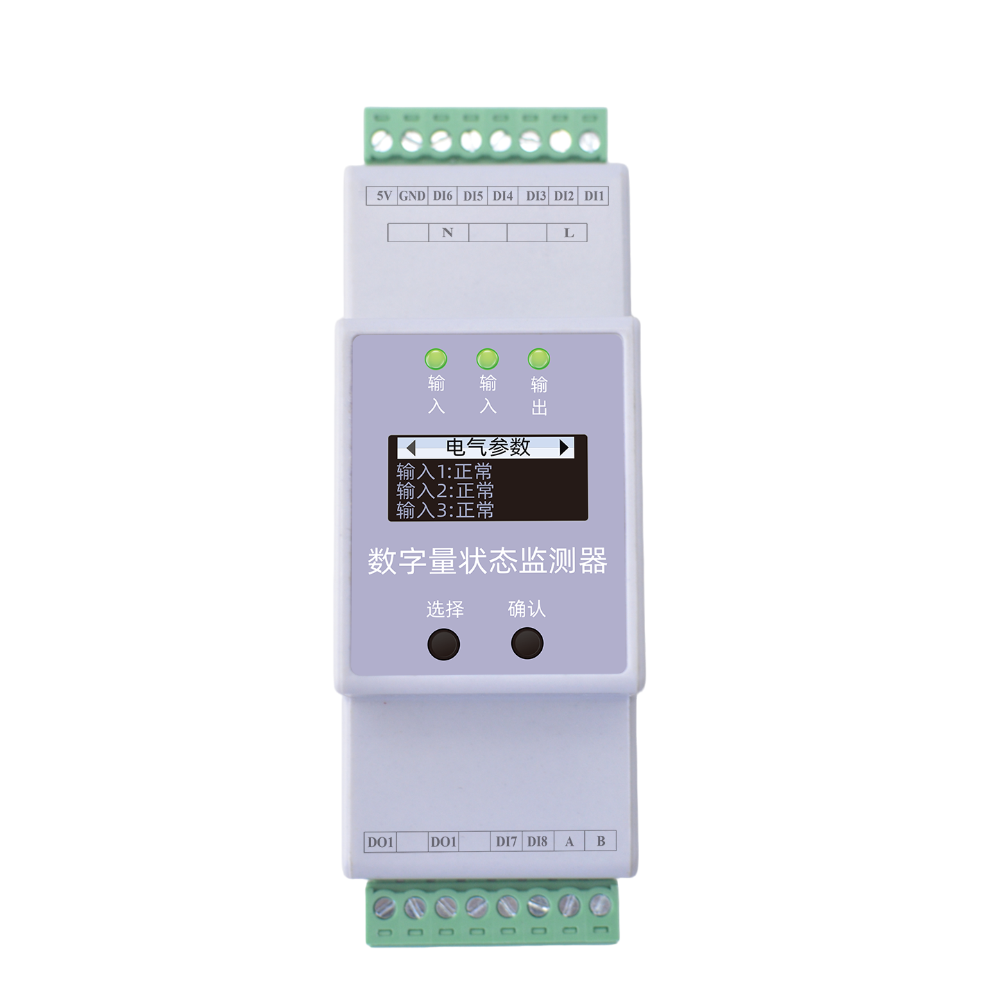
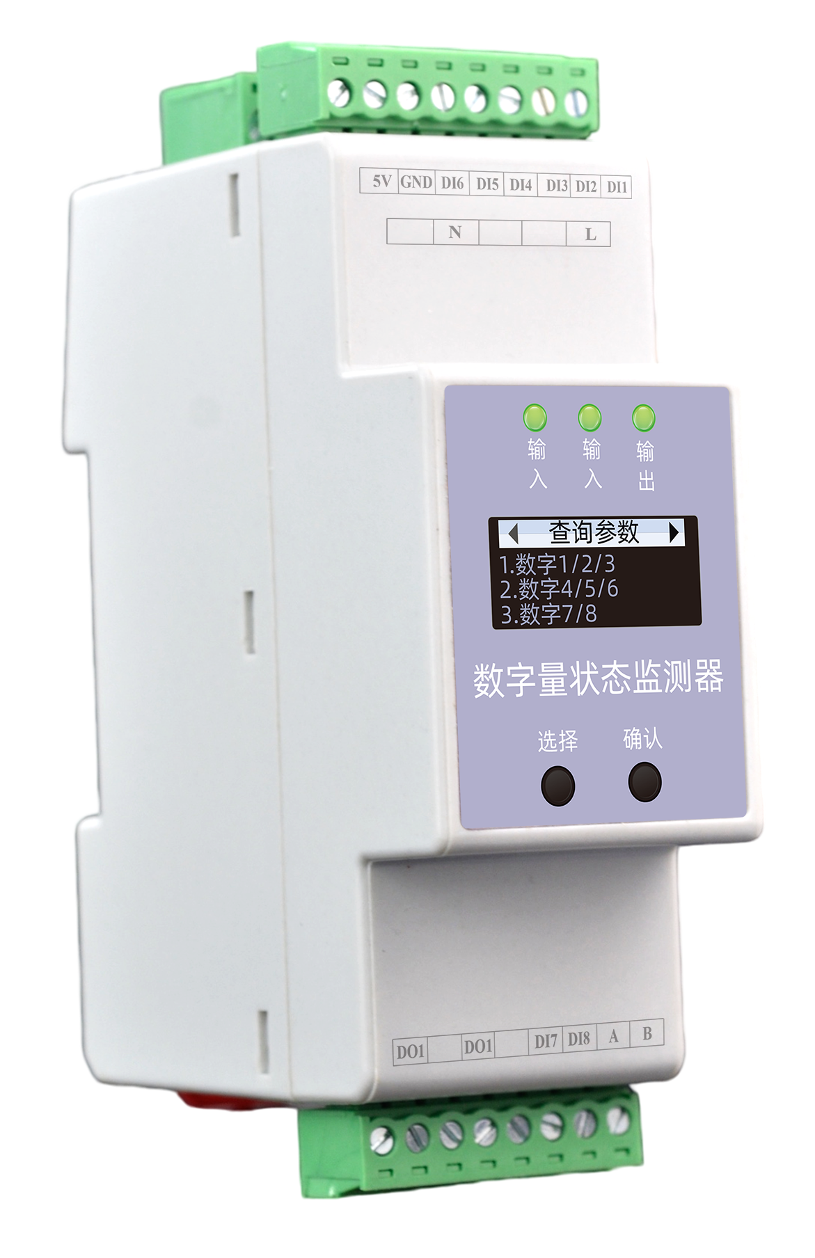
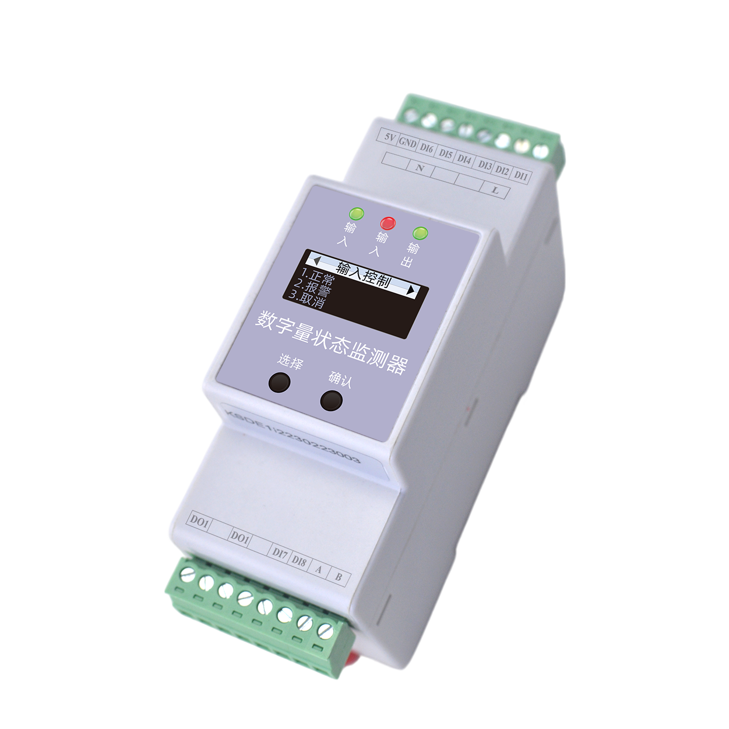
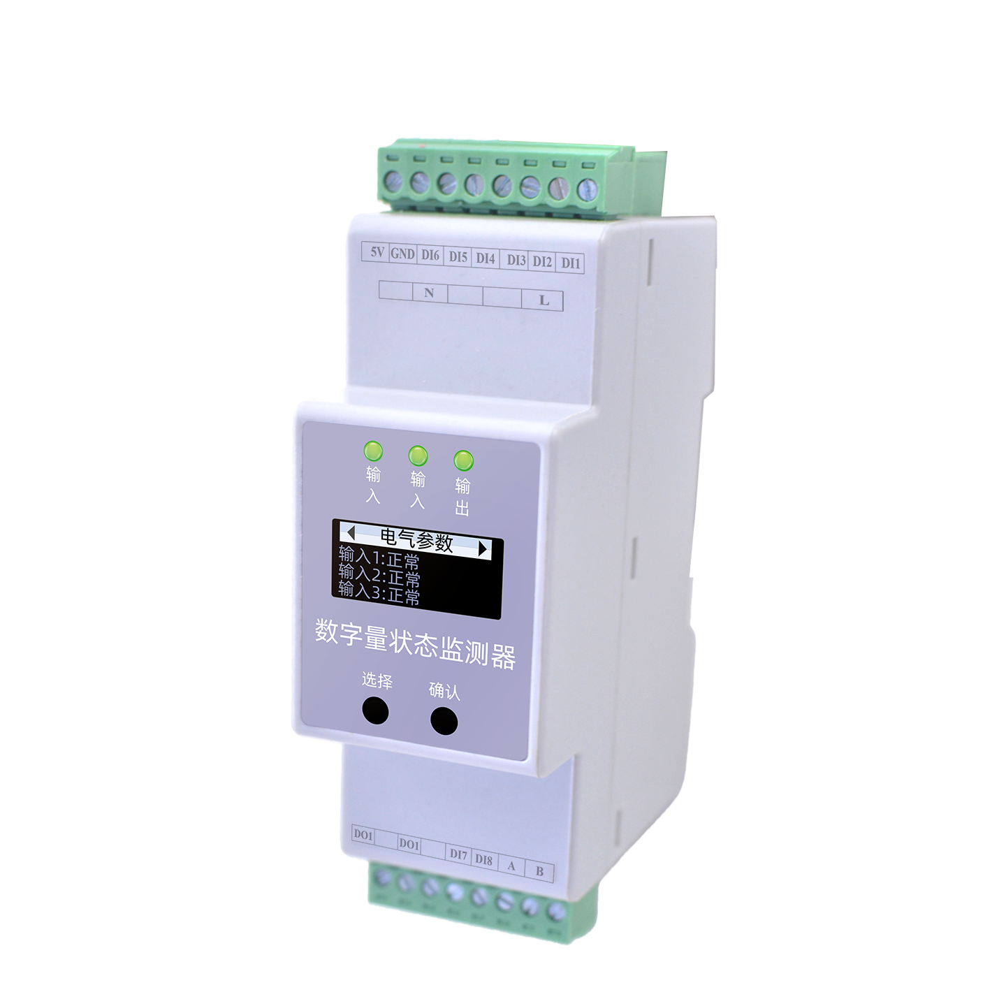
ESI Digital Status Monitor - monitoring
8-Channel Digital Status Monitoring, Error-Correction + High-Speed Sampling, Making Data "Reliable" and "Smart-Controllable"
Thoroughly solves existing problems such as "no alarm" and "false alarm". Uses error-correction algorithms, high-speed samplingsampleetc.Technology,Support8-channel dry-contact digital input,1-channel relay output,Integrating "measure, control, transmit, and intelligize" in one unit,widelyApplicationinmilitary,petrochemicalization,building,industrial park,railwaychannel,portport,airport,new energysourceetc.Field.
Product Overview
The ESI Digital Status Monitor uses proprietary software algorithm patented technology and embedded programs, paired with industrial-grade control chips, to deliver precise data processing and predictive analysis. Integrating "measure, control, transmit, and intelligize" in one unit, it is widely used in military, petrochemical, construction, industrial parks, railways, ports, airports, agriculture, mining, equipment, meteorology, water utilities, environmental protection, renewable energy and other fields.
Thoroughly solves existing problems such as "no alarm" and "false alarm" using error-correction algorithms, high-speed sampling and other technologies, making data "reliable" and "smart-controllable".
Core Monitoring Capabilities
- 8-Channel dry-contact digital input, independently configurable, precise status monitoring.
- Error-Correction + High-Speed Sampling, accurate, fast and stable data, enabling early prediction.
- 1-channel relay output, supports linkage control, quick response to on-site applications.
- OLED display + physical buttons, RS485 communication, Modbus, 36mm compact width.
Product Features
Accurate Data
High-speed chips capture key parameters accurately, quickly, and stably, enabling early prediction while removing unnecessary parameters such as current and voltage monitoring.
Key Parameters Expansion
Split-core high-precision sensors operate stably under strong electromagnetic interference.
All-Climate Sensor
Supports 3-channel residual current monitoring with independent configuration; 2-channel DI input and 1-channel relay output; threshold settings. Quickly adds more monitoring functions and quantities based on on-site application characteristics.
Comprehensive Acquisition
Supports linkage control; standard OLED display and physical buttons for convenient on-site query and configuration; RS485 communication, Modbus; 36mm compact width, easy to deploy even in tight spaces.
Compact and Flexible
36mm compact width design, DIN rail mounting, suitable for various compact installation scenarios.
Selection Guide
Model Naming Rules
| Model | Power Supply | Display | DI Inputs | Relay Output | RS485/Modbus |
|---|---|---|---|---|---|
| ESI-12110-R | External 5V | OLED | 8 | 1 | Yes |
| ESI-22110-R | 220V | OLED | 8 | 1 | Yes |
Technical Parameters
Basic Parameters
| Operating Voltage | DC 4.75~5.25V (5V) or AC 180~250V (220V) |
| Power Consumption | ≤2W |
| Operating Temperature | -20℃~70℃ |
| Operating Humidity | <95% |
| Weight | 150g |
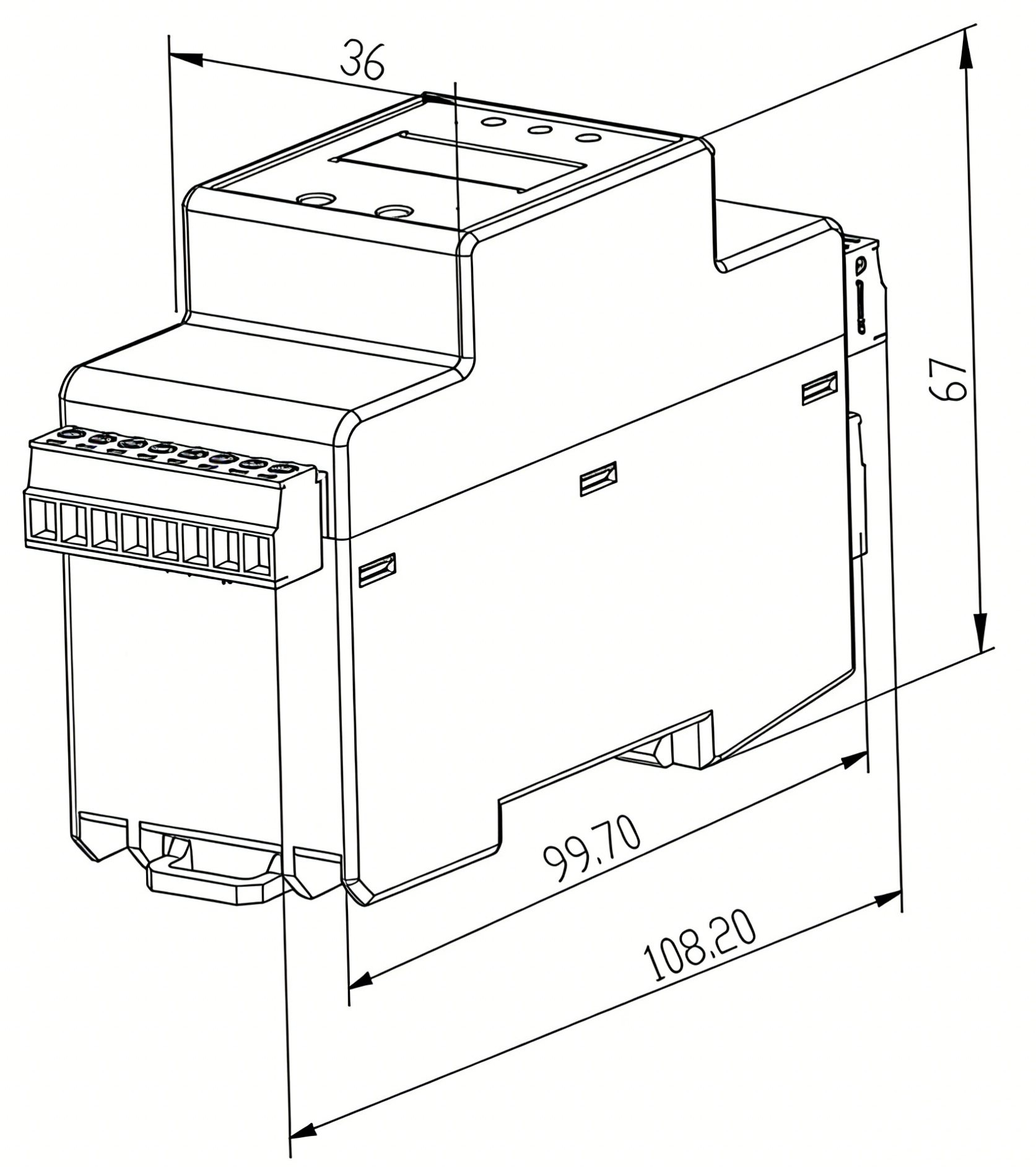
| Dimensions | 36×110×69mm (L×W×H) |
| Enclosure Material | Thermoplastic UL94V0 |
| Protection Rating | IP20 |
| Mounting | Standard 35mm DIN rail |
| Display | OLED |
| Communication | RS485 |
| Protocol | Modbus |
Monitoring Functions
| DI Input | Dry contact input, built-in power |
| DO Output | Relay output; contact capacity: AC250V/3A, DC30V/3A; normally open contact |
Installation Instructions
Installation Dimensions
Interface Diagram
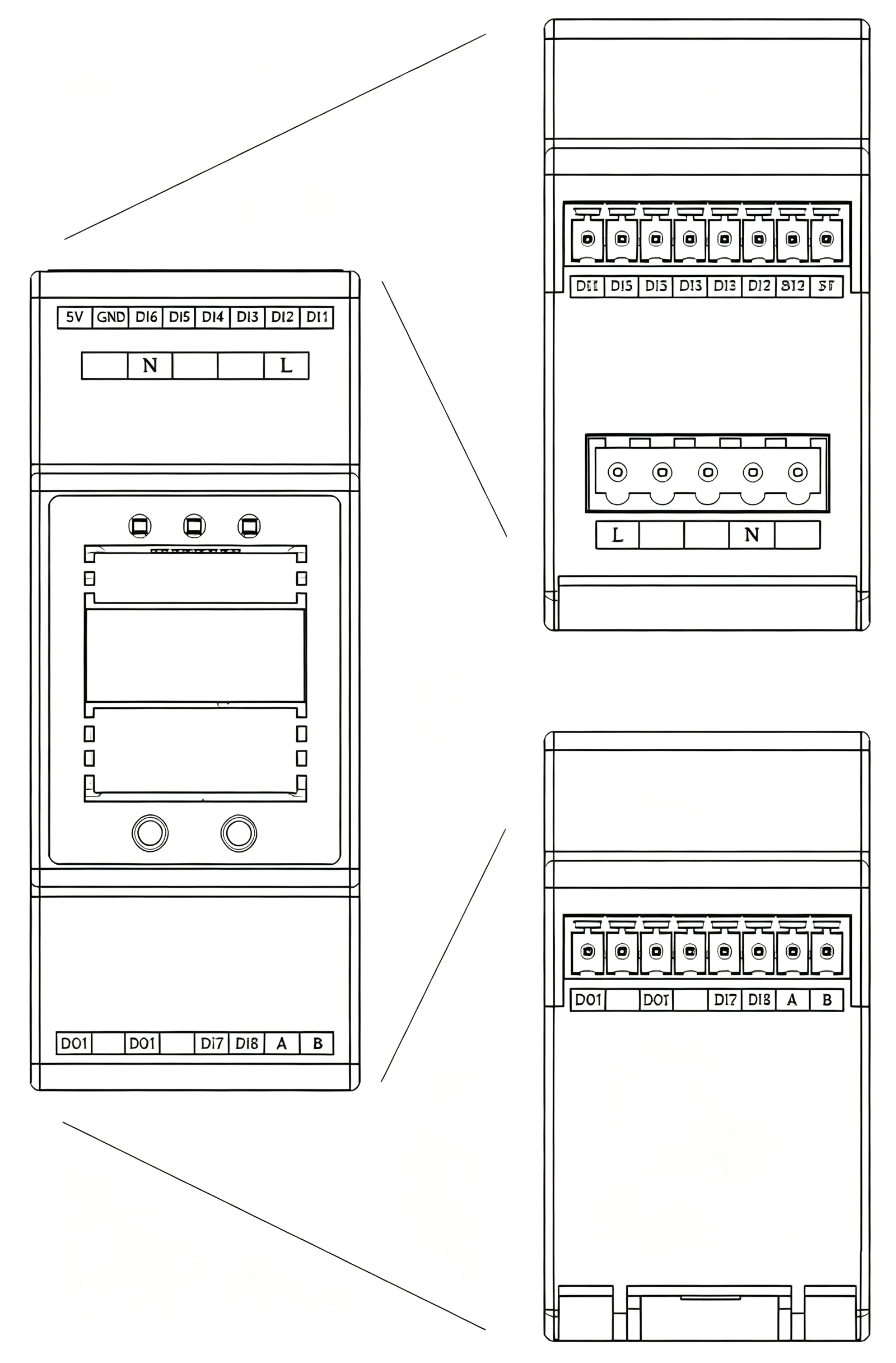
Wiring Definition
| Terminal | Definition |
|---|---|
| L1 | Live wire |
| N | Neutral wire |
| 5V | 5V DC power input |
| GND | 0V |
| A | RS485 A |
| B | RS485 B |
| DO1 | Output (relay, no polarity) |
| DO1' | Output' (relay, no polarity) |
| DI1 | DI 1 (other end to GND, no polarity) |
| DI2 | DI 2 (other end to GND, no polarity) |
| DI3 | DI 3 (other end to GND, no polarity) |
| DI4 | DI 4 (other end to GND, no polarity) |
| DI5 | DI 5 (other end to GND, no polarity) |
| DI6 | DI 6 (other end to GND, no polarity) |
| DI7 | DI 7 (other end to GND, no polarity) |
| DI8 | DI 8 (other end to GND, no polarity) |
Note: 220V AC input and 5V DC input are mutually exclusive.
Key Points
- Definition: The ESI Digital Status Monitor is FEXLINK's electrical monitoring device for acquiring switch/digital signals.
- Core Capabilities: Multi-channel digital input acquisition for monitoring breaker, contactor and relay status; supports RS485 upload.
- Scenarios: Suitable for digital-signal monitoring of distribution-cabinet breaker status and equipment run status.
- Related Products: ESA Electrical Safety Terminal, FG Smart Gateway, SFA Multi-Element Controller.
Frequently Asked Questions
Product FAQ
What is ESI Digital Status Monitor?
The ESI Digital Status Monitor is FEXLINK's electrical monitoring device for acquiring switch/digital signals.
What scenarios does ESI Digital Status Monitor apply to?
Suitable for digital-signal monitoring of distribution-cabinet breaker status and equipment run status.
How does ESI Digital Status Monitor differ from traditional solutions?
Compared with analog monitoring, the ESI focuses on digital signal acquisition, ideal for discrete signals such as switch status and alarm contacts.
How is ESI Digital Status Monitor installed and integrated?
DIN-rail mount inside the distribution cabinet, wire digital signals to the corresponding terminals, and connect the RS485 bus.
How can I purchase FEXLINK products or request a demo?
Submit requirements via the Contact page on the FEXLINK website, or call +86-755-8653-6148 to request a demo and selection consultation; engineers will propose a matched solution and quotation based on your scenario.
Related Products
ESC Leakage Current Monitoring Module
Error-correction + high-speed sampling, 3-channel independent residual current monitoring, split-core high-precision sensors.
ESP Neutral-Ground Voltage Monitor
Real-Time neutral-ground voltage monitoring, high-precision dynamic algorithm + error-correction.
ESF Electrical Fire Monitoring Module
Residual Current + 4-channel temperature monitoring, patented algorithm prediction, linkage control.
FEXLINK Business Scope
FEXLINK 微物联,专注配电场景电气安全与数字能源技术研发。我们以多维精准感知与智能算法为核心,通过端侧感知芯片、多维电气时序特征算法、三层电碳大模型,实现雷电防护、接地监测、电气隐患识别;同步完成配电计量、电能质量分析、回路级碳排核算。面向老旧柜体与工业配电,构建从现场采集、本地芯片推理到云端电碳智能中枢的端云协同体系,赋能能源安全管控、能效优化与低碳数字化落地。