Power Distribution Safety Monitoring for a Large Data Center
Deploying ESA electrical safety monitoring alarm devices, ESB electrical safety monitoring terminals, EST temperature sensors and ESX products to perform 7x24h online electrical safety monitoring of key scenarios including data center power distribution systems, UPS, rack PDU, and precision air conditioning, with Real-Time perception of leakage current, temperature and current anomalies, safeguarding power continuity and stable operation of IT equipment in the data center, and protecting cloud services and digital infrastructure safety.
01 · BACKGROUND
Customer Background
Enterprise Type
A large data center operating enterprise, primarily engaged in third-party data center colocation services, cloud infrastructure services and CDN business. Its customers cover multiple industries including internet, finance, government affairs and manufacturing, imposing extremely stringent requirements on power continuity and SLA (Service Level Agreement), with typical availability targets above 99.99%.
Data Center Grade: Tier III/IV · Rack Count: subject to site survey
Facility Scale
The data center includes key facilities such as main computer room, UPS battery room, distribution room, diesel generator room and precision air conditioning room, with a large number of racks and high single-rack power density (some high-density racks reaching 30kW+). The power distribution system adopts a 2N redundant architecture with dense distribution circuits and large fluctuations in power load.
Rack Count: subject to site survey · Total Power Capacity: Hazard warning
Industry Position
As national critical digital infrastructure, the data center must strictly comply with mandatory standards including GB 50174 Code for Design of Data Centers, GB/T 2887 General Specification for Computer Site, and TIA-942 Standard for Data Center Infrastructure. Indicators such as PUE, availability and energy efficiency are supervised by the Ministry of Industry and Information Technology and industry regulators.
Compliance Standards: GB 50174 / GB/T 2887 / TIA-942
02 · CHALLENGES
Business Challenges
Complex Power Distribution System with Dense Circuits
The data center adopts a 2N redundant power distribution architecture, involving multi-level distribution from utility power intake, UPS, column header cabinets to rack PDUs, with dense circuits and complex topology. Failure at any level may affect IT load Power Supply. Traditional manual inspection can hardly achieve high-frequency full coverage of all critical circuits.
Overheating Risks in UPS Batteries and Distribution Cabinets
UPS battery banks, distribution cabinet busbars, and circuit breaker contacts carry high current over long periods and are prone to localized overheating due to poor contact or aging, causing electrical fire or UPS failure risks. Without continuous online temperature monitoring, overheating hazards are difficult to detect in advance and may evolve into power interruption incidents.
Rack PDU Overload and Three-Phase Imbalance
High-density rack PDUs carry significant power and are prone to overload or three-phase imbalance caused by business fluctuations, affecting PDU lifespan and potentially triggering circuit protection to power off the rack. Existing DCIM systems have incomplete coverage of Real-Time current and temperature monitoring at terminal PDUs, unable to detect overload risks in advance.
Compliance Audit and SLA Evidence Collection Difficulties
Data center compliance audits and customer SLA assessments require complete, continuous and traceable Power Supply and electrical safety monitoring data. Paper records and discrete data cannot meet the compliance audit and customer SLA report requirements of standards such as GB 50174 and TIA-942.
03 · SOLUTION
Solution
System Architecture Diagram

Note: This is a technical illustration. Architecture: sensing layer → edge & network layer (ESX Intelligent Edge Computing Gateway) → platform layer (FEXCloud IoT Cloud Platform).
Deployed Product List
| Product Name | Model | Quantity | Function |
|---|---|---|---|
| ESA Multi-Parameter Smart Meter | ESA | Configured per point | Deployed in UPS output distribution cabinets and column header cabinets, Real-Time monitoring of residual current, cable temperature, overload and other electrical safety parameters |
| ESB Three-Phase Imbalance Monitor | ESB | Configured per point | Deployed in rack PDU and precision air conditioning distribution boxes, collecting multi-element data including leakage current, temperature, current and voltage |
| EST Multi-Channel Temperature Controller | EST | Configured per point | Attached to key heating points such as UPS battery poles, busbars, circuit breaker contacts and PDU sockets, achieving high-precision continuous temperature monitoring |
| ESX Intelligent Edge Computing Gateway | ESX | Configured per point | Deployed in diesel generators and STS switching cabinets, comprehensively monitoring backup power electrical status and switching reliability |
| FEXLINK Cloud Platform | Cloud 3.0 | 1 Set | Data aggregation, visualization, alarm push, O&M work orders, compliance report auto-generation, SLA report support |
Note: Product quantities follow the point-based configuration principle; final quantities are subject to site survey and the implementation plan.
Network Topology
Sensing Layer: ESA electrical safety monitoring alarm devices are deployed in UPS output distribution cabinets and column header cabinets; ESB electrical safety monitoring terminals are deployed in rack PDU and precision air conditioning distribution boxes; EST temperature sensors are attached to key heating points such as UPS battery poles / busbars / circuit breaker contacts / PDU sockets; ESX electrical safety monitoring devices are deployed in diesel generators and STS switching cabinets, achieving full-scenario electrical safety monitoring of the data center power distribution system.
Network Layer: Each sensing terminal connects to the nearest ESX intelligent edge computing gateway via RS485 bus (Modbus-RTU protocol). ESX gateways uplink to the DCIM O&M network via data center internal LAN / 4G cellular network, with key nodes supporting dual-link redundant backup to ensure data transmission reliability.
Platform Layer: Data aggregates to the FEXLINK Cloud platform (privately deployed in the data center O&M room), providing web and mobile visualization dashboards, Real-Time alarms, historical trend analysis, O&M work order dispatch, compliance report and SLA report auto-generation, multi-role permission management (O&M / facilities / customer service) and more.
Integration Layer: The cloud platform connects with existing data center DCIM, BMS (Building Management System), and dynamic environment monitoring systems via standard REST API / Modbus TCP / SNMP protocols, enabling data sharing and linked alarms, and incorporating them into the unified O&M work order workflow.
04 · IMPLEMENTATION
Implementation Process
Site Survey & Solution Design
Engineers visit the data center site to survey the 2N power distribution architecture, UPS circuits, column header cabinets, and rack PDU distribution, outputting a point list and system deployment plan.
Timeline: per project schedule
Equipment Installation & Wiring
ESA/ESB/ESX installed in each distribution cabinet and PDU, EST temperature sensors attached to key heating points, ESX intelligent edge computing gateways centrally deployed, completing RS485 bus wiring and power connection. Construction is scheduled outside business peak hours to avoid disrupting IT load operation.
Timeline: per project schedule
System Commissioning & Platform Integration
Configure ESX gateway acquisition parameters and upload cycle, complete FEXLINK Cloud platform account setup, point binding, alarm threshold setting, and integration debugging with existing DCIM/BMS/dynamic environment monitoring systems.
Timeline: per project schedule
Trial Operation & Personnel Training
System trial operation and data accuracy calibration, training of O&M, facilities and customer service personnel on platform operation, alarm handling, work order flow and SLA report export, completing project acceptance and delivery.
Timeline: per project schedule
05 · RESULTS
Application Effects
7×24h
All-Weather Online Monitoring
Key areas
Monitoring Point Coverage Count
Online inspection
Reduced Manual Inspection Hours
Hazard warning
Advance Hazard Warning Count
subject to site survey
PDU Overload Avoidance Count
Auto
Compliance & SLA Report Auto-Generation Rate
Application Value
"subject to site survey The customer testimonial for this case will be added after customer confirmation. The testimonial will cover comparison of electrical hazard detection capability before and after system deployment, the value of PDU overload early warning, and improvements in SLA compliance audit efficiency."
— Qualitative statement based on solution design objectives
06 · RELATED PRODUCTS
Related Product Recommendations
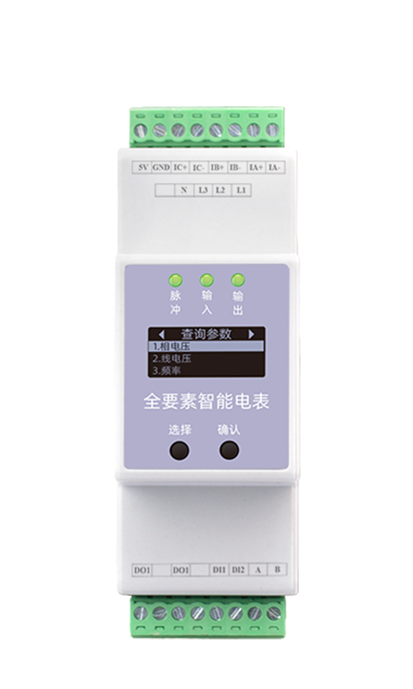
Electrical Safety
ESA Multi-Parameter Smart Meter
Residual Current · Cable Temperature · Overload Monitoring
View Product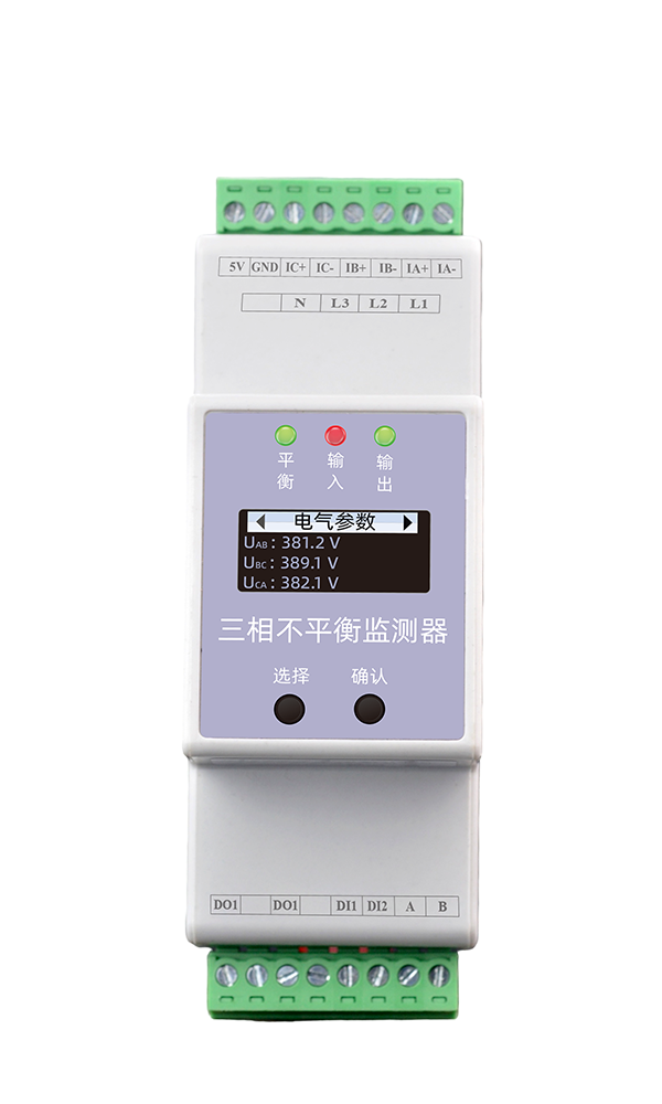
Electrical Safety
ESB Three-Phase Imbalance Monitor
Multi-Element Acquisition · High Precision · Terminal Coverage
View Product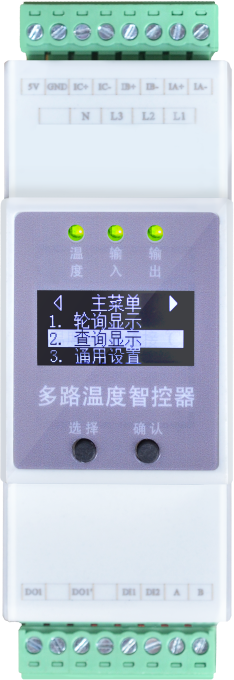
Electrical Safety
EST Multi-Channel Temperature Controller
UPS Battery · Busbar · High-Precision Temperature Measurement
View Product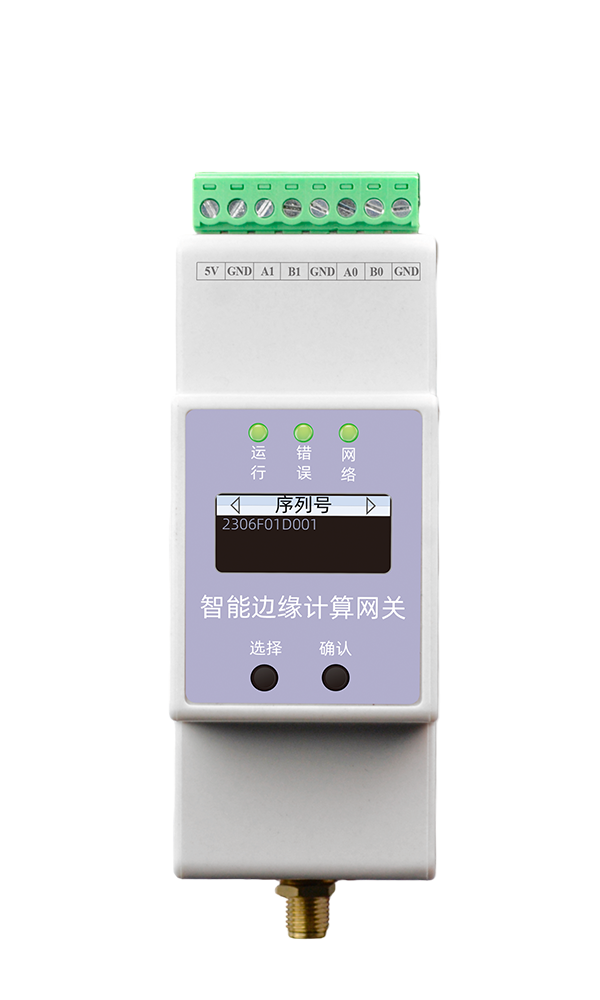
Digital Energy
ESX Intelligent Edge Computing Gateway
Multi-Protocol Aggregation · Edge Computing · Dual-Link
View Product07 · RELATED CASES
Related Cases
Tertiary Hospital Electrical Safety and Fire Monitoring
Online electrical safety monitoring of hospital power distribution systems, operating rooms, ICU and other key scenarios.
View DetailsIndustrial Park Smart Energy Monitoring
Electrical safety and energy efficiency management for industrial park distribution rooms, factory buildings, energy storage and other scenarios.
View DetailsGrid Enterprise Smart Monitoring
7x24h online electrical safety monitoring of substations and distribution facilities.
View DetailsGet Similar Solution
If your data center has similar power distribution safety monitoring needs, please contact us for a customized solution. The FEXLINK technical team will provide an end-to-end IoT solution based on your data center grade, rack scale, and SLA requirements.
FEXLINK Business Scope
FEXLINK 微物联,专注配电场景电气安全与数字能源技术研发。我们以多维精准感知与智能算法为核心,通过端侧感知芯片、多维电气时序特征算法、三层电碳大模型,实现雷电防护、接地监测、电气隐患识别;同步完成配电计量、电能质量分析、回路级碳排核算。面向老旧柜体与工业配电,构建从现场采集、本地芯片推理到云端电碳智能中枢的端云协同体系,赋能能源安全管控、能效优化与低碳数字化落地。