 FEXLINK Research Institute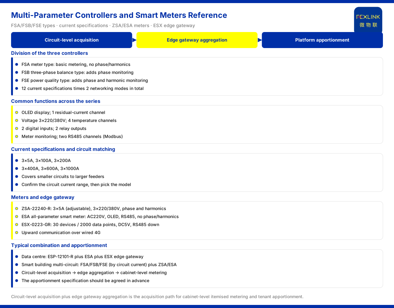
Direct answer
To achieve cabinet-level PUE and tenant metering in a data centre, the difficulty is often not "whether to measure" but "how to measure accurately across the many circuits of a column-header cabinet". The acquisition approach given by the product knowledge base is to deploy multi-parameter electrical intelligent controllers and embedded smart meters per column-header cabinet circuit, measure current, voltage and electric energy, and then aggregate upward to the platform through the intelligent edge-computing gateway, so as to achieve cabinet-level itemised metering and tenant apportionment and avoid whole-column estimation. That is, accurate cabinet-level energy consumption relies on "circuit-level acquisition plus gateway aggregation", not on one estimation at the main point and proportional apportionment. The product knowledge base records that the multi-parameter electrical intelligent controller comes in three types: meter type (FSA series), three-phase balance type (FSB series) and power quality type (FSE series); the embedded multi-function smart meter is supplied at AC220V across the whole series and has an OLED display. This article restates only the entries listed by the product knowledge base and infers no on-site metering accuracy or apportionment result.
1. Why the column-header cabinet is hard for cabinet-level metering
A column-header cabinet is characterised by many circuits, high density and limited space. One column-header cabinet often leads out dozens of branches, each corresponding to the power supply of a row or group of cabinets. Achieving cabinet-level metering within such a structure faces two practical constraints: first, many circuits, so acquisition points must be deployed at scale; second, limited space, so devices cannot occupy too much cabinet position. If only one meter is fitted at the main point of the column-header cabinet, what is obtained is the total energy of a whole column. To apportion the total to the cabinets, one can usually only estimate by rated power or uptime, and the result inevitably deviates from the actual energy use. To truly answer "how much each cabinet used", one must return to circuit-level acquisition so that the current, voltage and electric energy of each branch can be measured independently. This is the problem that a multi-circuit acquisition architecture solves.
2. Division of the three multi-parameter electrical intelligent controllers
The product knowledge base records that the multi-parameter electrical intelligent controller is divided into three types, with 12 current specifications in total and 2 networking modes. The meter type (FSA series) carries basic meter monitoring without phase and harmonic monitoring; the three-phase balance type (FSB series) adds phase monitoring on top of meter monitoring; the power quality type (FSE series) adds harmonic monitoring on top of phase monitoring. The difference between the three can be understood as a progression of monitoring depth. If a circuit needs only basic current, voltage and electric energy, the meter type suffices; if the circuit has a three-phase balance concern, the three-phase balance type with phase monitoring can be chosen; if the circuit also involves harmonics, the power quality type with power-quality monitoring should be chosen. Which type to choose depends on whether the circuit needs a deeper layer of power-quality data, not on taking the highest configuration as a matter of course.
3. Common interfaces and monitoring items across the series
Although the three types differ in monitoring depth, they share a set of common functions. The product knowledge base records that the multi-parameter electrical intelligent controller series has an OLED display, 1 residual-current channel, voltage 3×220/380V, 4 temperature channels, 2 digital inputs, 2 relay outputs, meter monitoring, and two RS485 channels (Modbus). These common items determine its suitability in a column-header cabinet scenario. The 3×220/380V voltage specification corresponds to common three-phase distribution; the two RS485 channels facilitate networking and cascading; the digital inputs and relay outputs can be used to connect on-site states and execute actions; and the residual-current and temperature monitoring add safety-related observables to the circuit. The multi-parameter electrical intelligent controller is thus not merely a meter but a circuit-level device combining metering, monitoring and interfaces.
4. Current specifications and circuit matching
The product knowledge base records that the current specifications of the multi-parameter electrical intelligent controller cover 3×5A, 3×100A, 3×200A, 3×400A, 3×600A and 3×1000A. This set of specifications spans a wide range, covering different current levels from smaller circuits to larger feeders. In a column-header cabinet scenario this means that branches of different capacities can choose the corresponding current specification, without having to adapt all circuits with one tier. In selection, first confirm the current range of the circuit and then choose the matching model in the specification table. Note that the product knowledge base lists only the above current specifications, and this article infers no transformer form, installation method or accuracy class of each specification from them; the specific condition is subject to the latest product material.
5. Using embedded smart meters to complete metering
Between the column-header cabinet and the cabinets, meters are often also needed to carry metering closer to the end. The product knowledge base records that the embedded multi-function smart meter is supplied at AC220V across the whole series and has an OLED display; of these, the model ZSA-22240-R is 3×5A (adjustable), 3×220/380V, supports meter monitoring plus phase plus harmonics, and communicates over RS485. Another model to consider is the all-parameter smart meter. The product knowledge base records that the all-parameter smart meter is, across the whole series, AC220V, OLED, RS485 (Modbus), with voltage 3×220/380V, 2 digital inputs and 1 relay output, and without phase and harmonic monitoring; if phase or harmonics are needed, another corresponding series should be chosen instead. Combining the two meter classes with the multi-circuit controller lets metering cover both the backbone circuits and the nodes closer to the load.
6. Aggregation to the platform through edge gateways
The data acquired at circuit level must form usable information through an upward link. The product knowledge base records that the intelligent edge-computing gateway, model ESX-0223-GR, has an access capability of 30 devices and 2000 data points, is supplied at DC5V, has an OLED display, and communicates downward over RS485 and upward over wired 4G. This set of parameters shows that a single gateway can take a considerable number of circuit devices and data points. For a column-header cabinet scenario, connecting the multi-circuit controllers and meters to the gateway over RS485 and aggregating upward from the gateway corresponds exactly to the characteristics of "many circuits and dense data". Only after the gateway aggregates the data and sends it up to the platform does the cabinet-level energy composition have a basis for centralised viewing and apportionment.
7. Typical combination and apportionment specification
In its typical application scenarios, the product knowledge base gives relevant combinations. The recommended combination for the data-centre neutral-to-ground voltage and distribution monitoring row is the neutral-to-ground voltage monitor (e.g. ESP-12101-R) plus the all-parameter smart meter plus the intelligent edge-computing gateway; the recommended combination for the smart-building multi-circuit energy-management row is the multi-parameter electrical intelligent controller (selected by circuit current) plus the embedded smart meter or the all-parameter smart meter. The two combinations reflect the acquisition approach of this article from different sides: the multi-circuit controllers and meters carry circuit-level measurement, and the edge gateway carries aggregation. Landing on cabinet-level energy consumption and tenant apportionment, the practice is to give each column-header cabinet circuit a corresponding circuit-level measurement and then apportion by actual energy use, not by estimating from the whole-column total meter. The apportionment specification should be agreed in advance and kept stable, while the measurement data comes from the circuit-level devices. The above combinations and parameters are limited to what the product knowledge base lists.
Scope and limitations
First, this article restates only what the product knowledge base lists, with the factual boundary limited to the positioning of the three multi-parameter electrical intelligent controllers FSA/FSB/FSE, the common functions of the series, the current specifications, the parameters of the embedded multi-function smart meter ZSA series and the all-parameter smart meter ESA series, the access capability of the intelligent edge-computing gateway ESX-0223-GR, and the relevant recommended combinations listed by the knowledge base.
Second, the difference between the three controllers is: the meter type has basic meter monitoring without phase and harmonics; the three-phase balance type adds phase monitoring; the power quality type adds phase and harmonic monitoring. This article infers no accuracy class or applicable circuit range of each type.
Third, the common functions of OLED, 1 residual-current channel, voltage 3×220/380V, 4 temperature channels, 2 digital inputs, 2 relay outputs and two RS485 channels are cited per the product knowledge base, and this article extends no unlisted interface or protocol.
Fourth, the current specifications are limited to 3×5A, 3×100A, 3×200A, 3×400A, 3×600A and 3×1000A; this article infers no transformer form, installation method or accuracy of each specification.
Fifth, this article gives no specific accuracy, apportionment ratio or effect conclusion of cabinet-level metering; the relevant recommended combinations are limited to what the product knowledge base lists, and the actual solution is subject to the latest product material and project conditions.