 FEXLINK Research Institute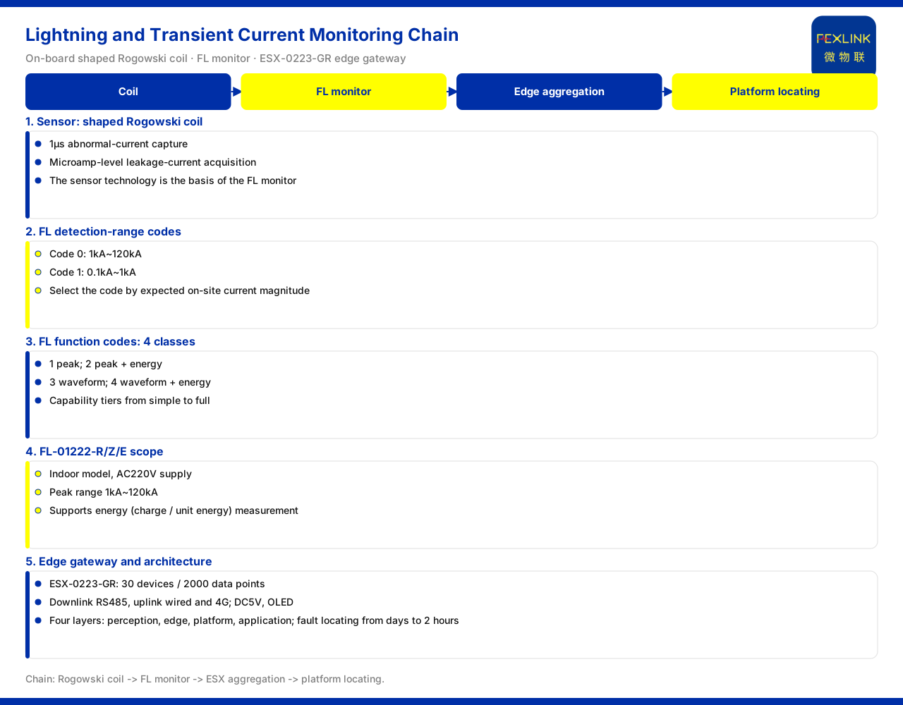
Direct answer
The difficulty in monitoring transient current and lightning current lies in capturing anomalies of extremely short duration. According to the product knowledge base, the core sensor technology is an on-board special-shape Rogowski coil, with a 1-microsecond abnormal-current capture capability and support for microamp-level leakage-current acquisition. Based on this technology, the FL series is the lightning current / transient current monitor, whose detection-range code 0 corresponds to 1kA to 120kA and code 1 to 0.1kA to 1kA; there are 4 function codes: 1 for peak, 2 for peak+energy, 3 for waveform and 4 for waveform+energy. Taking FL-01222-R/Z/E as an example, it is an indoor model with AC220V supply, a peak range of 1kA to 120kA and support for energy (charge/unit energy) measurement. The uplink edge side is carried by the intelligent edge-computing gateway (e.g. ESX-0223-GR), whose access capability is 30 devices/2000 data points, with RS485 downlink and Ethernet and 4G uplink, using DC5V supply and an OLED display. The following explains the knowledge-base entries.
1. Core sensor: the on-board special-shape Rogowski coil
The knowledge base expresses the core sensor technology as an on-board special-shape Rogowski coil and gives two capabilities: 1-microsecond abnormal-current capture and microamp-level leakage-current acquisition. The former points to the time resolution of transient quantities, and the latter to the detection floor for small currents.
These two capabilities correspond to two different classes of monitoring need. The 1-microsecond capture faces abnormal currents of extremely short duration, used so that transient events are not missed; microamp-level leakage-current acquisition faces very small leakage currents, used to observe weak signals such as insulation state. The knowledge base lists both under the Rogowski coil technology, and this article relays them as they are without inferring the complete range or bandwidth specification.
It must be emphasised that the sensor technology is the foundation of the FL monitor, and this article describes the two in separate sections to explain the hierarchical relationship between "technology" and "product," not to equate them.
2. Detection ranges of the FL lightning current / transient current monitor
On top of the Rogowski coil, the knowledge base lists the FL lightning current / transient current monitor. Its detection range is distinguished by code: code 0 corresponds to 1kA to 120kA, and code 1 to 0.1kA to 1kA. That is, the same product line provides two detection intervals of different magnitude through codes, one facing larger lightning currents and one facing smaller transient currents.
This coded distinction has direct meaning for selection: first determine the code by the current magnitude expected at the site, then settle on the corresponding model. This article lists the two ranges as the knowledge base gives them and does not infer other specifications beyond the code.
3. Function codes of FL: 4 classes
Besides detection range, FL also distinguishes capability by function code. The knowledge base records 4 function codes: 1 for peak, 2 for peak+energy, 3 for waveform and 4 for waveform+energy. The four classes can be understood as combinations of two dimensions: whether waveform is included and whether energy is included. To judge magnitude only, choose a peak class; to record waveform shape, choose a waveform class; to account for energy, choose one of the two classes with energy.
This arrangement layers the functions from fewer to more, making it easy to converge by the recording depth a project requires. This article relays the four function classes as the knowledge base gives them and does not infer the sampling parameters or recording capacity of each.
The four function classes are not four devices standing side by side but capability grades on the same product line, from simpler to more complex. This article lists them as the knowledge base gives them and does not infer the storage method or export format of each grade.
4. Concrete specifications of FL-01222-R/Z/E
The knowledge base gives a more concrete record of FL-01222-R/Z/E: an indoor model, AC220V supply, a peak range of 1kA to 120kA, and support for energy (charge/unit energy) measurement. Read together with the function codes above, this model falls in the "peak+energy" capability interval: it reports both peak and energy.
The model suffix R/Z/E stands alongside the same set of specifications in the knowledge base, and this article cites it as given without inferring what each of the three suffixes corresponds to. It should be noted that this article states only the model's indoor attribute, supply, peak range and energy measurement, and does not extrapolate its protection rating or installation method.
5. Edge side: the ESX-0223-GR intelligent edge-computing gateway
Monitoring data needs to be aggregated and uplinked. The knowledge base records that the ESX-0223-GR intelligent edge-computing gateway has an access capability of 30 devices/2000 data points; its downlink communication is RS485, its uplink communication is Ethernet and 4G, and it uses DC5V supply and an OLED display.
These parameters define the gateway's place in the link: downward it accesses perception-side devices over RS485, upward it sends data to the platform over Ethernet or 4G, and the access scale is in terms of 30 devices and 2000 data points. This article states this as the knowledge base gives it and does not infer its computing or storage specifications.
6. Place in the four-layer architecture and value scope
The knowledge base summarises the monitoring system as a four-layer architecture: perception layer, edge layer, platform layer and application layer. The perception layer includes the FS/FR/FL/ES series monitoring modules and sensors such as the Rogowski coil, and the edge layer includes the FG/ESX/CW gateways. Accordingly, the Rogowski coil and the FL monitor belong to the perception layer, and the ESX gateway belongs to the edge layer; the two connect over RS485 and then feed upward into the platform layer and application layer.
On the value side, the knowledge base records that the applicable industries of the Taiyi intelligent control hub system include data centers, and that among its quantified values the fault-location time is shortened from several days to 2 hours. Read together with the preceding link, the correspondence from perception to value can be seen: the Rogowski coil and FL record transient events, ESX aggregates and uplinks them, and the platform side then supports fault location. This article only relays this value scope and does not read it as a commitment regarding the location time at any given site.
7. Selection and implementation order
The entries can be drawn together into one order. First, confirm whether the monitoring object is transient current or leakage current: transient and lightning currents are carried by the FL series, and leakage-current acquisition relies on the microamp-level capability of the Rogowski coil. Second, determine the detection-range code by the current magnitude expected at the site (0: 1kA to 120kA; 1: 0.1kA to 1kA). Third, determine the function code by the recording depth (1 peak, 2 peak+energy, 3 waveform, 4 waveform+energy). Fourth, confirm the installation environment and supply, such as FL-01222-R/Z/E being an indoor model at AC220V. Fifth, choose the edge gateway ESX-0223-GR (30 devices/2000 data points) by the access scale and verify its downlink RS485 and uplink Ethernet and 4G communication methods.
Scope and limitations
- The content of this article is limited to the existing statements of the product knowledge base on entries related to the Rogowski coil, the FL lightning current / transient current monitor, the ESX intelligent edge-computing gateway and the four-layer architecture, and does not extend to parameters, certifications or cases not listed in the knowledge base.
- The 1-microsecond abnormal-current capture and microamp-level leakage-current acquisition of the Rogowski coil are knowledge-base scopes, and this article does not infer its complete range or bandwidth.
- The detection-range codes of FL (0: 1kA to 120kA; 1: 0.1kA to 1kA) and the function codes (4 classes) are cited as the knowledge base gives them; the indoor attribute, AC220V supply, peak range and energy measurement of FL-01222-R/Z/E are likewise limited to the material.
- The access capability (30 devices/2000 data points), communication methods (downlink RS485, uplink Ethernet and 4G) and supply and display of ESX-0223-GR are knowledge-base scopes.
- The four-layer architecture and the fault-location time scope are relayed as the knowledge base gives them, and this article does not infer the product list or deployment quantities of each layer.
- This article constitutes no commitment regarding any unlisted indicator; actual capability is subject to the latest product documentation and the project solution.