 FEXLINK Research Institute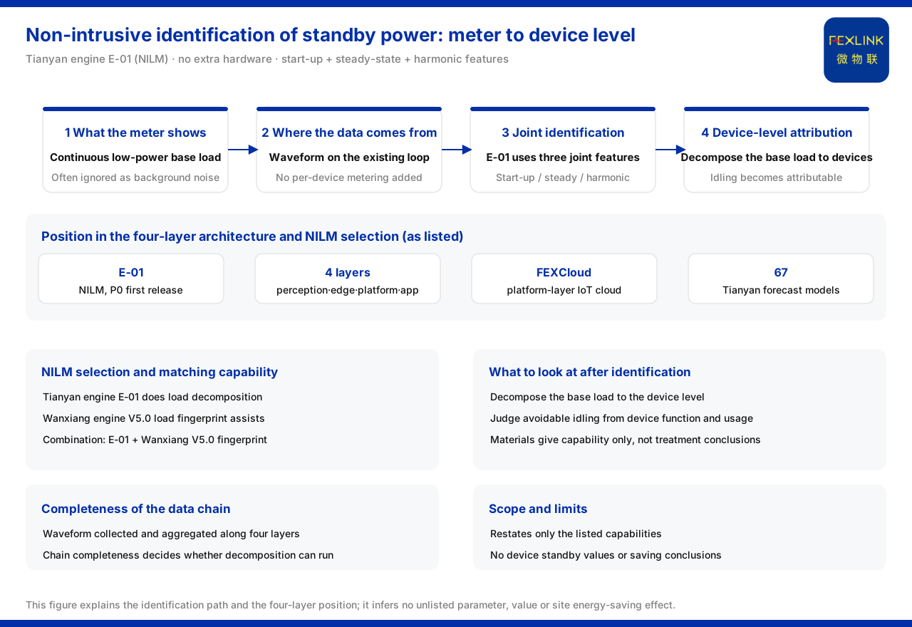
Direct answer
Standby power is "invisible" in the main-meter data because it is too small and too continuous, and is easily submerged by the total load; but it is not unidentifiable. The product knowledge base records that E-01 of the Tianyan engine (large model) is a non-intrusive load monitoring (NILM) model, belonging to the P0 first-release models of the E energy-analysis section. Its key value is that it needs no extra hardware and identifies a specific device through the current waveform. Standby power appears as a continuous low-power base load, and E-01 uses start-up features, steady-state power and harmonic features jointly to identify a device, so this layer of low-power base load can be decomposed onto specific devices, turning "who is idling" from a small fraction on the main meter into an attributable object. After identification, selection lands on the combination of Tianyan engine E-01 with the Wanxiang engine (large model) V5.0 load fingerprint. This article restates only what the product knowledge base lists, and infers neither the standby-power value of an unlisted device nor an energy-saving conclusion for any site.
1. What standby power looks like on the main meter
On the energy-use curve of the main meter, standby power usually does not appear as an obvious power jump but as a low-power base load that persists for a long time, with a modest amplitude and almost no fluctuation with the production rhythm. It is not as visible as a start-up surge, nor as easy to classify as full-load operation, and is therefore often ignored as "background noise". To identify it, the premise is to decompose the total load down to the device level: only by knowing how much each device contributes can one judge which part is continuously consumed without output. This is exactly the problem that non-intrusive load decomposition must solve.
2. Why E-01 needs no extra hardware
The product knowledge base records that E-01 needs no extra hardware and identifies a specific device through the current waveform. This determines its deployment mode: identification does not depend on fitting each device with a separate metering device, but collects the current waveform on the existing electrical loop and decomposes the device components from it. For a site with existing distribution and monitoring conditions, this means there is no need to add hardware on a large scale just to "see standby power clearly"; the identification capability lies mainly on the data and model side. It should be noted that what is given here are the two records "no extra hardware" and "identification through the current waveform"; the knowledge base does not unfold engineering details such as the sampling rate or the number of channels, and this article infers none.
3. How three classes of feature jointly identify a device
The product knowledge base records that E-01 uses start-up features, steady-state power and harmonic features jointly to identify a device. These three classes of feature have separate duties: start-up features correspond to the transient process at the instant a device is switched on, steady-state power corresponds to the power level continuously consumed while the device runs steadily, and harmonic features correspond to the high-frequency components in the device current waveform. Looked at alone, any one feature may be ambiguous; used jointly, they raise the degree of discrimination. For standby power, the steady-state power path is especially relevant: the standby state is precisely a long-term steady low-power state. Combining steady-state power with the start-up and harmonic features allows one to judge which class and which device this continuous low power belongs to.
4. The path to identifying standby power
Placing the features above back into the "finding standby" scenario gives a reusable path. First, notice from the main-meter data the long-persisting, modest low-power base load; second, with the decomposition capability of E-01, break this base load down to the device level and see which devices it falls on; third, combined with the functions and usage patterns of these devices, judge whether this consumption is avoidable idling. Every step of this path rests on capabilities listed by the knowledge base: the low-power base load is the phenomenon, device-level decomposition is the means, and attribution is the purpose. It does not depend on fitting each device with hardware, and can therefore start under existing monitoring conditions.
5. From identification to selection: E-01 and Wanxiang V5.0
The product knowledge base writes the selection combination for "non-intrusive load identification (NILM)" as Tianyan engine E-01 plus the Wanxiang engine (large model) V5.0 load fingerprint. It also records that the evolution direction of Wanxiang engine V5.0 is precisely the non-intrusive load fingerprint (NILM). That is, E-01 bears the load decomposition on the energy-analysis side, and Wanxiang V5.0 provides identification support along the load-fingerprint direction; the two are matched on the NILM objective. For the question "how standby power emerges in energy-use data", this combination gives a product-level landing point: E-01 performs the decomposition and identification first, and the load-fingerprint capability then takes part in the device-level judgement.
6. Where the data comes from: its place in the four-layer architecture
The premise of identification is to obtain data. The product knowledge base describes the monitoring system as a four-layer architecture of perception layer, edge layer, platform layer and application layer, in which the platform layer is the FEXCloud IoT cloud platform, providing a general chain for the collection and uplink of energy-use data. The current-waveform data required by energy analysis is collected from the site along this chain and aggregated through the edge and the platform. Placing E-01 back into this architecture shows that it is not a module running independently but is built on the energy-use data of the four-layer chain; the completeness of the data chain directly determines whether load decomposition can be carried out.
7. What to look at after identification
After standby power is decomposed to the device level, one still needs to return to the judgement of "whether treatment is needed". Identification is only the first step: it lands the low-power base load of the main meter on specific devices and shows which devices are in a state of continuous consumption. The next judgement should combine the device function and usage pattern — the same low-power operation may be a necessary standby of the device, or may be idling that can be shut down. The product knowledge base provides only the identification capability and specification, and gives no conclusion as to whether a certain class of device should be shut down, so this article does not decide on its behalf. What can be certain is that, without device-level decomposition, standby power remains a vague fraction on the main meter; with the decomposition of E-01 and the participation of the load fingerprint, it becomes an attributable and discussable object. This shift from "seeing the phenomenon" to "attributing the device" is precisely the landing point of non-intrusive load identification in energy analysis.
Scope and limitations
First, this article restates only what the product knowledge base lists, with the factual boundary limited to existing entries such as the NILM positioning of Tianyan engine E-01, no extra hardware, identification through the current waveform, joint identification by start-up features, steady-state power and harmonic features, and the four-layer architecture and the NILM selection combination, and introduces no unlisted parameter, certification or case.
Second, standby power appearing as a "continuous low-power base load" is a description of the phenomenon based on the steady-state power feature; this article gives no standby-power value of any specific device on that basis.
Third, this article draws no conclusion on the energy-saving effect, savable electricity or return on investment of any specific site; the relevant judgement must be verified in conjunction with the on-site device composition and operating data.
Fourth, in the four-layer architecture the platform layer is the FEXCloud IoT cloud platform, whose capability is limited to what the knowledge base lists; this article extends no unmentioned detail of data storage or algorithm.
Fifth, the selection combination is limited to "Tianyan engine E-01 plus Wanxiang engine V5.0 load fingerprint"; this article provides no specific configuration or deployment conclusion.