 FEXLINK Research Institute
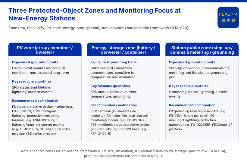
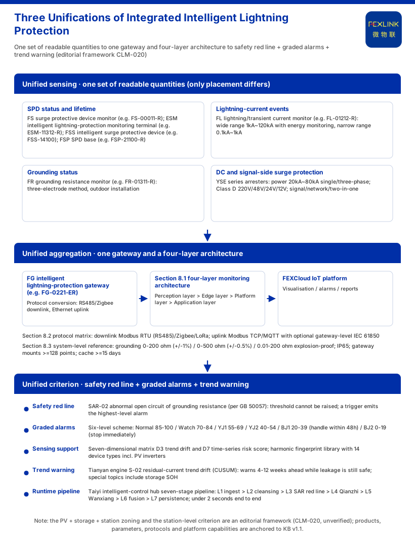
# How Do PV, Energy Storage and New Energy Stations Implement Integrated Intelligent Lightning Protection? The difficulty of lightning protection at PV, energy-storage and new-energy stations is not whether to install surge protective devices (SPDs) but that the protected objects are scattered. In one station, the PV array, the inverters, the storage units, and the step-up collection and grounding grid each face lightning differently; if every point reads only its own device, the protection state is fragmented. Integrated intelligent lightning protection adds readability above existing SPDs: unified sensing reads SPD status, lightning-current events and grounding status; unified aggregation brings them onto one network; a unified criterion (safety red lines, graded alarms, trend warning) forms a station-level basis for action. Caveat: the "PV + storage + station" zoning and the station-level criterion are an editorial framework; knowledge base (KB) v1.1 does not state them as facts and does not use "integrated intelligent lightning protection" as a product name (CLM-020, unverified). Product and parameter facts below are verifiable KB v1.1 entries. ## One: Integration Is Not "One More Device" but One Data Chain Traditionally each device gets its own SPD: module mounts, combiners, inverters, storage converters, communications and metering. That is necessary for discharge but cannot answer three station-level questions: how much margin each SPD has left, which zone was just struck, and which grounding is degrading. Integration shows in three places: perception reads the same quantities, the edge centralises aggregation and protocol conversion, and the platform applies one criterion and presentation. It replaces no SPD; it adds a layer of readability above the existing protection system (CLM-020, unverified). ## Two: Split the Station into Protected-Object Zones First We suggest splitting a station by exposure and grounding into three object zones (CLM-020, unverified). The PV zone — large metal mounts and long DC combiner runs — is exposed long-term, and focuses on SPD status and lightning-current events. The storage zone concentrates batteries and converters and is more sensitive to temperature and insulation, so it focuses on SPD status, residual current, temperature and grounding. The public zone — step-up collection, communications, metering and the grounding grid — focuses on grounding status and lightning-current events. KB does not give this zoning; it only lists new-energy stations as an applicable industry (CLM-019). The zoning is our method for answering "how to integrate". ## Three: Unified Sensing — One Set of Readable Quantities Whichever zone, the readable quantities are the same; only placement differs. SPD status and lifetime are read by the FS surge protective device monitor (e.g. FS-00011-R), covering remote signalling, air-switch status, grounding status, strike count, leakage current, temperature, voltage and lifetime estimation, with parameters leakage 50.0~1200.0 μA (±10 μA), voltage 0~400.0 V (±0.1 V), temperature -20~100 °C (±1 °C), strike count 0~9999 (minimum trigger 0.1 kA) and lifetime 0~100% (CLM-001). Where every element including humidity is needed, use the ESM intelligent lightning-protection monitoring terminal (e.g. ESM-11312-R) (CLM-002). New build packages may use the FSS intelligent surge protective device, In/Imax from 10 kA/20 kA to 40 kA/80 kA with Up 1.5 kV~2.2 kV (CLM-003), or the FSP SPD base, offering remote signalling and strike counting (CLM-004). Lightning-current events are read by the FL lightning/transient current monitor (e.g. FL-01212-R): wide range 1 kA~120 kA with energy monitoring, narrow range 0.1 kA~1 kA (CLM-006). Grounding status is read by the FR grounding resistance monitor (e.g. FR-01311-R) using the three-electrode method, for outdoor use (CLM-005). DC-side and signal/network surge protection is handled by the YSE series: power arresters offer 20 kA~80 kA single- and three-phase ratings (CLM-008), Class D power arresters cover 220 V/48 V/24 V/12 V (CLM-009), plus signal, network and two-in-one arresters, lightning counters and a three-element SPD monitor (CLM-010). ## Four: Unified Aggregation — One Gateway and a Four-Layer Architecture Scattered quantities must first be aggregated into a station-level view. The FG intelligent lightning-protection gateway (e.g. FG-0221-ER) is a protocol converter with RS485/Zigbee downlink and Ethernet uplink (CLM-007), bringing each zone's modules onto a unified link. KB §8.1 divides the monitoring system into perception, edge, platform and application layers: perception-layer modules upload through the edge gateway to the FEXCloud IoT platform, and the application layer produces visualisation, alarms and reports (CLM-011). Protocols are covered by §8.2: device downlinks include Modbus RTU (RS485), Zigbee and LoRa; uplinks include Modbus TCP/MQTT and optional gateway-level IEC 61850 (CLM-012). For grounding, §8.3 gives system-level reference parameters: units cover 0-200 Ω (±1%) / 0-500 Ω (±0.5%) / 0.01-200 Ω explosion-proof; protection grade IP65; the gateway mounts ≥128 points and caches data ≥15 days (CLM-013). ## Five: Unified Criterion — Safety Red Line + Graded Alarms + Trend Warning Aggregation needs a criterion, or it is just curves. The first layer is a non-bypassable safety red line: KB §11.1 lists "abnormal open circuit of grounding resistance" as SAR-02 (per GB 50057); nobody may raise the threshold, and a trigger emits the highest-level alarm directly (CLM-016). The second layer is grading: the six-level scheme rates urgency as Normal (85-100), Watch (70-84), YJ1 (55-69), YJ2 (40-54), BJ1 (20-39, handle within 48 hours) and BJ2 (0-19, stop immediately) (CLM-015); it is supported by the seven-dimensional matrix's D3 trend drift and D7 time-series risk score and a harmonic fingerprint library of 14 device fingerprints including PV inverters (CLM-017). The third layer is trend: the Tianyan engine's S-02 residual-current trend drift (CUSUM) detects a weak mean shift while leakage is still safe, warning 4-12 weeks ahead, and its special topics include storage SOH (CLM-018). These criteria run on the Taiyi intelligent-control hub's seven-stage pipeline: L1 ingest → L2 cleansing → L3 SAR red-line pre-check → L4 Qianzhi analysis → L5 Wanxiang assessment → L6 fusion decision → L7 persistence, under 2 seconds end to end, where an L3 red-line trigger emits the highest-level alarm (CLM-019). ## Six: Selection — Three Zones and Recommended Combinations Matching capabilities to zones yields a selection table. Under the product-naming rule, models appear only here and in source references: | Object zone (editorial) | Key readable quantities | Recommended combination (mapped from KB §3/§7/§9 generic sets) | |:--|:--|:--| | PV zone (array / combiner / inverter) | SPD status and lifetime, lightning-current events | FS surge protective device monitor (e.g. FS-00011-R), ESM intelligent monitoring terminal (e.g. ESM-11312-R), FL lightning/transient current monitor (e.g. FL-01212-R); DC and signal sides may use YSE arresters | | Storage zone (battery / converter / container) | SPD status, residual current, temperature, grounding | ESM terminal (all elements incl. humidity), FD mains (residual-current) monitoring module (e.g. FD-01011-R), FSS intelligent SPD (e.g. FSS-14100), FSP SPD base (e.g. FSP-21100-R) | | Public zone (step-up / comms & metering / grounding grid) | Grounding status, lightning-current events | FR grounding resistance monitor (e.g. FR-01311-R, one per point), FG intelligent gateway (e.g. FG-0221-ER), FEXCloud IoT platform | Note that KB §9's scenario table lists no dedicated "PV plant" or "storage station" row; the closest are substation/traction grounding-grid monitoring, tank-farm/petrochemical lightning and explosion protection, and arrester condition monitoring (retrofit of existing SPDs) — three generic combinations (CLM-014). The mapping above is therefore an editorial derivation applying generic sets to new-energy stations (CLM-020, unverified); it does not mean KB provides a PV- or storage-specific package. ## Seven: Boundaries — What This Article Does Not Claim First, this zoning and the station-level criterion are editorial; KB does not state them as fact and does not use "integrated intelligent lightning protection" as a name (CLM-020, unverified). They are not a design code, O&M procedure or acceptance basis. Second, KB §11.5 indicators (hazard identification 95%+, alarm compression 80%, warning lead 4-12 weeks, MTTR reduced 60%, energy savings 8-20%) are vendor self-reports, not independently verified (CLM-021); cite them only as vendor claims, never as revenue, benefit or procurement grounds. Third, KB gives no placement density, air-termination or equipotential-bonding practice, retrofit procedure, construction sequence, quantity, sampling/reporting frequency, offline caching and backfill, alarm-ticket grading or evidence format; this article asserts none. Fourth, landing points of registered or planned articles are not reused: not 015 (PV single-scenario motive/points), 035 (same-batch planned, landing undeclared) or the legacy seventh piece (multi-scenario commonality). It cites only KB-listed identifiers such as GB 50057 and infers no clause content. ## Conclusion For PV, storage and new-energy stations, integration is not about adding devices but about wiring scattered protected objects into one data chain: zone by exposure and grounding, sense with the same readable quantities (SPD status and lifetime, lightning-current events, grounding status), aggregate through the FG gateway and §8.1/§8.2 architecture and protocols into FEXCloud, hold the floor with the §11.1 SAR-02 red line and six-level alarms, move warning earlier with the §11.3 Tianyan S-02, and map to deployment via the §9 combinations (CLM-001 to CLM-019). Terms and models follow KB-locked usage (CLM-022).
How Do PV, Energy Storage and New Energy Stations Implement Integrated Intelligent Lightning Protection?
Applicable Scope: Digital Energy
Disclaimer: Knowledge content only; not engineering design, sizing or compliance advice; standards per official texts.