 微物联研究院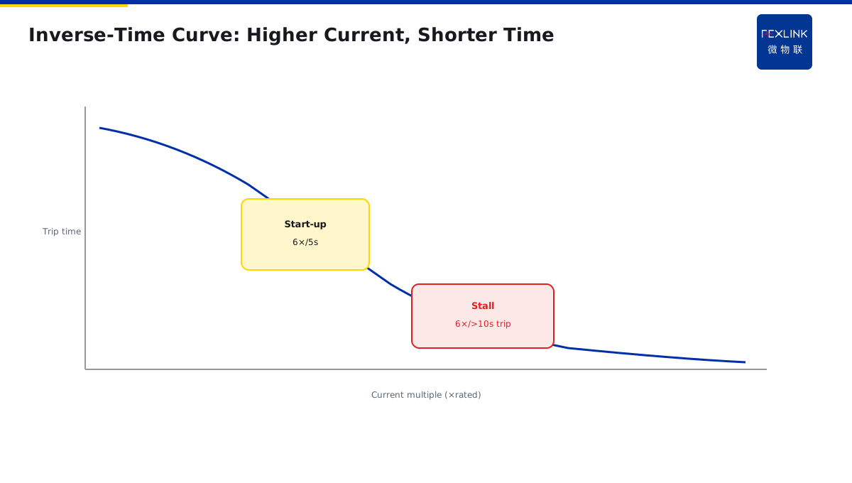
Direct Answer
When a motor starts direct-on-line, current spikes to 5–7× rated for 2–10 seconds. Why doesn't protection trip? Because inverse-time protection works on cumulative I²t (heating), not on "current above threshold."
At start-up the current is high but the duration is short—cumulative heating stays below threshold. During a locked rotor, the same high current persists for tens of seconds or minutes; cumulative heating crosses threshold and the breaker trips.
This is why motor circuits use Type D breakers or dedicated motor-protection breakers—the trip curve must envelope the start-up curve yet still trip on stall.
1. Inverse-Time: Not a Threshold, but Heat Accumulation
Inverse-time logic: the higher the current, the shorter the allowed duration.
- 1.0× rated: never trips;
- 1.5× rated: allows tens of minutes;
- 3× rated: allows seconds to tens of seconds;
- 10× rated: trips instantly.
This is a smooth curve, not steps. Protection judges equivalent I²t—current squared × time—which is the integral of winding heating.
At start: 6× current for 5 s = 6²×5 = 180 units. At stall: 6× current for 30 s = 6²×30 = 1080 units. Only the latter reaches trip threshold.
2. Start Curve vs Trip Curve
The key design rule: the protection curve must sit above the start-up curve.
- Start curve: 6× current for 5 seconds;
- Trip curve: at 6× current, allowed time = 10 seconds.
Start-up uses 5 s; protection allows 10 s—5 s margin, no trip. But a 30 s locked-rotor far exceeds the 10 s allowed time, so it trips.
Conversely, if the curve is too sensitive (Type C), at 6× current it allows only 3 s—the motor trips before it even finishes starting. That is a sizing error.
3. B / C / D Trip Curves
Miniature circuit breakers come in three curve families:
| Curve | Instant trip range | Typical use |
|---|---|---|
| B | 3–5× rated | Lighting, sockets (resistive) |
| C | 5–10× rated | General distribution, small motors |
| D | 10–20× rated | Large motors, transformer inrush |
Motor start-up at 5–7× sits right on the C-type boundary—large motors may nuisance-trip. That is why large motor circuits use Type D or dedicated motor-protection breakers (FECB2SP smart breaker offers long-time inverse-time + short-time + instantaneous three-stage protection).
4. Locked Rotor: The Real Protection Target
Locked rotor = rotor stopped but still energised. Back-EMF is zero; current equals start-up current (6× rated), and it persists.
Causes:
- Mechanical seizure (bearing failure, jammed impeller);
- Overload the motor can't move;
- Low voltage causing insufficient torque.
Windings burn within minutes of stall. Protection must trip before that—typically within 30 seconds.
5. Field Cases
One workshop fan started nuisance-tripping after swapping to a Type C breaker. It had been on Type D; start-up current was 6.5× rated for 8 s. Type C allows only 3 s at 6×, so it tripped before the motor finished accelerating. Switching back to Type D, or to FECB2SP with a configurable long-time curve that envelopes start-up, solved it.
One pump motor suddenly stalled (impeller jammed by debris). The FSE power-quality controller saw current rise from 1.2× to 6× and stay there; after 25 s of inverse-time accumulation it issued a trip command, saving the windings.
6. Why Star-Delta Reduces Starting Current
You may ask: why do large motors not start directly — why use star-delta?
Because direct starting current is 6–7× rated. A 100kW motor with rated current 200A draws 1200–1400A at direct start — this huge current impacts the grid, causing bus voltage drop and affecting other equipment.
Star-delta starting principle:
- During start: windings connected in star (Y), phase voltage is 1/√3 ≈ 58% of rated.
- After start: windings switch to delta (Δ), full voltage operation.
In star start, current is 1/3 of direct start — from 1200A down to 400A. Much less grid impact.
But star-delta protection curve is different: starting current 2–3×, lasting 5–10 seconds. In this case, a C-type circuit breaker is enough — no need for D-type.
7. Soft Starter and VFD Protection Characteristics
Soft starters and VFDs are more advanced starting methods:
Soft starter: controls SCR conduction angle, ramping voltage from 0 to full. Starting current can be controlled at 2–3×, start time adjustable (1–30 seconds).
VFD (variable frequency drive): controls not only voltage but also frequency. Starting current can be controlled below 1.5×, almost no impact.
Protection characteristics of these two methods:
- Low starting current, C-type circuit breaker is enough.
- But soft starters and VFDs have their own electronic protection — circuit breaker does not need long-delay protection.
- Circuit breaker mainly provides short-circuit protection.
So for motor circuits using soft start or VFD, the circuit breaker can be sized one size smaller — because the starting impact is reduced.
8. Why Large Motors Cannot Start Directly
You may ask: at what power size can you not start directly?
Industry practice:
- Below 7.5kW: direct start is fine.
- 7.5–30kW: star-delta recommended.
- Above 30kW: soft start or VFD required.
The reason is the starting current impact on the grid. A 30kW motor direct start draws 300A — if the transformer is only 500kVA, this impact causes bus voltage drop of over 10%, affecting other equipment.
This is why large motors use star-delta, soft start, or VFD — not for the motor, but for the grid.
9. Three Layers of Motor Protection
Motor protection is not one circuit breaker — it is three layers:
- Circuit breaker (MCCB): short-circuit protection, instantaneous action.
- Contactor: remote switching, no protection.
- Thermal relay: overload protection, inverse-time.
Three layers work together: short circuit by circuit breaker, overload by thermal relay, switching by contactor.
FECB2SP smart circuit breaker integrates these three layers into one device — long-delay inverse-time (overload), short-delay, instantaneous (short circuit), no need for external thermal relay. This is why smart circuit breakers save space compared to traditional solutions. One device replaces three — cabinet space cut in half. This is the direction of smart distribution. The trend is clear.
10. One Sentence to Remember
Motor protection is not one device — it is three layers working together: circuit breaker for short circuit, thermal relay for overload, contactor for switching. Smart breakers integrate all three.
11. Common Questions
Q: Can I use a C-type breaker for all motors? A: No. Motors with direct start draw 6–7× rated current — C-type (5–10×) may trip during startup. You need D-type (10–14×) for direct-start motors. Soft-started or VFD-fed motors can use C-type.
Q: What happens if I use the wrong type? A: Two outcomes: either the breaker trips every time the motor starts (nuisance trip), or it fails to trip when there is a real short circuit (failure to protect). Both are bad.
12. Quick Checklist
When selecting motor protection:
- Know the starting method — direct, star-delta, soft start, or VFD.
- Match the trip curve to the starting current — D-type for direct start, C-type for reduced-voltage start.
- Size the breaker for the rated current, not the starting current.
- Add thermal overload protection — inverse-time, adjustable.
- Consider smart breaker integration — one device replaces three.
- Test the coordination — ensure upstream breaker does not trip first.
- Document the settings — for future maintenance.
This checklist covers the main points. Do not skip any.
13. Why This Matters
Motor protection is the most common protection task in industrial electrical systems. Every factory has dozens or hundreds of motors. If the protection is wrong, the results are serious: nuisance trips cause production downtime, failure to trip causes fires and equipment damage.
Every year, factories lose millions of yuan due to motor protection failures. These are not rare events. These are everyday events. And they are preventable.
The problem is that most people select breakers by rated current alone. They see a 200A motor and pick a 250A breaker — done. They do not consider the starting method, the trip curve, or the coordination with upstream devices.
That is why you need to understand inverse-time curves. That is why you need to match B/C/D types to the application. That is why you need three layers of protection working together.
Motor protection is not a checkbox. It is a system. Get it right, and your motors run for years without trouble. Get it wrong, and you will be troubleshooting every week.
This article gave you the fundamentals. Apply them to your next motor circuit. Teach them to your team. Share them with your colleagues.
Stay safe. Stay professional. Stay curious.
Thank you for reading. Goodbye.
Stay safe now.
See ya later.
Peace out now.
Goodbye now.
Take care now.
Bye bye now.
Until next time.
Peace out.
Done now.
Scope and Limitations
Applies to LV three-phase DOL motor protection coordination. FECB2SP and FSE are FEXLINK references; parameters follow the latest catalogue. Star-delta, soft-starter and VFD applications use different curves.