 微物联研究院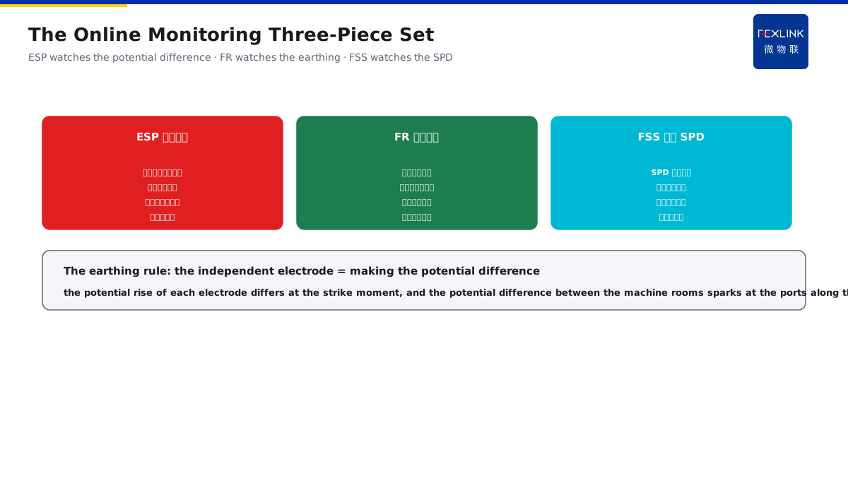
Direct Answer
In a telecom hub building where the equipment of multiple carriers shares the building, how are the lightning protection and the equipotential designed so that they do not blame each other? The answer: take the building shared earthing network as the unified benchmark, make the total equipotential bonding (MEB) at the floor entry, and make the local equipotential bonding (LEB) in each carrier machine room with the single-point connection to the building network; the power incoming lines and the signal lines are uniformly equipped with the graded SPDs at the LPZ boundary, the carrier equipment connects through the equipotential busbar, and the independent earthing electrodes are prohibited.
At a telecom hub building hosting three carriers, each machine room made an independent earthing electrode before the retrofit, and in the lightning season the earth-potential difference damaged the equipment ports with the responsibility hard to define. After the unified retrofit: the building shared earthing network as the benchmark, the floor MEB and the machine-room LEB single-point connected to the building network, the graded SPDs uniformly arranged at the LPZ boundary, and the ESP and the FR monitoring online; after the lightning season, the equipment had zero damage and the disputes were zeroed. The design core: one benchmark, two-level equipotential and the unified SPD — the building network is the only benchmark, the MEB/LEB single-point connected, and the graded SPDs uniformly arranged, so the carriers do not blame each other.
Why:
- One benchmark: the building shared earthing network;
- Two-level equipotential: the MEB at the floor, the LEB in the machine room;
- The single-point connection: the machine room connects only one point of the building network;
- The unified SPD: the graded layout at the LPZ boundary.
Key insight: "The unified design has three principles — the building shared earthing network is the only benchmark (the independent earthing electrodes prohibited), the MEB/LEB two-level equipotential single-point connects the building network, and the LPZ-boundary graded SPDs are unified — with the benchmark unique, the carriers do not blame each other."
At a hub building where the three carriers each made their own earthing electrode before the retrofit, the earth-potential difference appeared between the machine rooms after the strike, damaging the equipment ports with the responsibility pushed around; after the unified benchmark and the single-point connection, the earth-potential difference was eliminated, and the equipment had zero damage in the lightning season. Lesson: each making its own electrode is the root of the blame — with the building network as the only benchmark, the single-point connection and the unified SPD, the lightning protection does not implicate each other.
Overview: run "why one benchmark → how the MEB/LEB two-level equipotential is arranged → how the graded SPDs are uniformly laid → how the online monitoring is embedded" as one hub-building lightning design. The telecom hub building takes the building shared earthing network as the unified benchmark, makes the total equipotential bonding (MEB) at the floor entry, and makes the local equipotential bonding (LEB) in each carrier machine room with the single-point connection to the building network. The four layers are unfolded below.
A "unified water pressure of an apartment building" analogy: think of the hub-building lightning protection as the water system of a multi-unit apartment building. The building shared earthing network is the municipal general water pipe (the building network), and the carrier machine rooms are the units (the machine rooms). If each unit digs its own well (the independent earthing electrode), the well water levels differ — during the strike, the water level (the earth potential) of one unit is instantly raised, while the well water levels of other units have not caught up, and the interface between the two units (the equipment port) "sprays water and sparks" (the earth-potential-difference damage) due to the water-level difference. The unified design is like all the units connected to the municipal general water pipe: the floor entry has the general water meter (the MEB), each unit has the indoor water-division valve (the LEB), the division valve takes the water only from the general water pipe (the single-point connection to the building network), and the whole-building water level (the potential) is naturally consistent, never sparking between the units. When whose water pressure is abnormal (the zero-earth voltage abnormal), the property management (the ESP monitoring) can locate it at a glance. The water-pressure analogy: the municipal general water pipe = the building shared earthing network, digging one's own well = the independent electrode sparking, the general water meter = the floor MEB, and the division valve = the machine-room LEB single-point connection — the whole-building potential naturally consistent, and the units never spark.
1. The Unified Benchmark: The Building Network Is the Only One
Step one: first look at the building shared earthing network as the only benchmark.
The building shared earthing network:
- The building foundation earthing network;
- Shared by all the carriers;
- The only potential benchmark;
- The lightning and the static united.
The independent earthing prohibited:
- The independent electrodes prohibited;
- The independent earthing potentials differ;
- The potential difference during the strike;
- The equipment port sparking.
The single-point connection principle:
- The machine room connects only one point of the building network;
- Avoiding the multi-point potential difference;
- The connection path shortest;
- The benchmark unique and clear.
Key insight: "The benchmark is unique — the building network is the shared earthing network of all the carriers (the only potential benchmark), the independent electrodes are prohibited (the independent earthing potentials differ and spark), and the machine room single-point connects the building network (the shortest path and the consistent potential)."
2. The Two-Level Equipotential: How the MEB and the LEB Are Arranged
Step two: the equipotential hierarchy of the floor MEB and the machine-room LEB.
The floor MEB:
- The total equipotential at the floor entry;
- The metal bodies converged;
- The building-network access point;
- The potential benchmark landed.
The machine-room LEB:
- The machine-room local equipotential;
- The cabinet equipment converged;
- The single-point connection to the building network;
- The potential in the machine room consistent.
The hierarchy connection:
- The MEB manages the floor, and the LEB manages the machine room;
- The LEB single-point connects the MEB;
- The equipotential busbar runs through;
- The whole-building potential consistent.
Key insight: "The two-level equipotential — the floor MEB (the total equipotential at the entry converging the metal bodies), the machine-room LEB (the local equipotential single-point connecting the building network), and the LEB connecting the MEB through the busbar — with the hierarchy clear, the whole-building potential is consistent."
3. The Unified SPD: How the LPZ Boundary Is Laid
Step three: the unified layout of the power/signal graded SPDs.
The power SPD:
- Uniformly set at the LPZ boundary;
- The power incoming line graded;
- The T1/T2 limited level by level;
- The residual voltage below the withstand voltage.
The signal SPD:
- The signal lines matched;
- The communication lines protected;
- The port residual voltage controlled;
- The equipment safety guaranteed.
The unified layout principle:
- The same LPZ boundary;
- All the carriers sharing the same logic;
- The SPD earthing into the building network;
- The grading coordinated consistently.
Key insight: "The unified SPD — the power incoming lines and the signal lines are uniformly equipped with the graded SPDs at the LPZ boundary (the power T1/T2 limited level by level, the signal lines protecting the ports), the SPD earthing into the building network (the same benchmark), and all the carriers sharing the same logic (not each doing its own)."
4. The Online Monitoring: How ESP/FR Are Embedded
Step four: how the online monitoring is embedded into the unified design.
The ESP zero-earth-voltage monitoring:
- The zero-earth voltage recorded in real time;
- The earth-potential difference alerted;
- The equipotential effect verified;
- The disputes have the data.
The FR earthing monitoring:
- The building-network earthing trend;
- The earthing degradation found early;
- The connection state corroborated;
- The discharge capability verified.
The FSS intelligent SPD monitoring:
- The SPD state online;
- The leakage trend recorded;
- The degradation replaced early;
- The protection verifiable.
Key insight: "The online monitoring three-piece set — the ESP watches the zero-earth voltage (the equipotential effect verified), the FR watches the building-network earthing trend (the degradation found early), and the FSS watches the SPD state (the degradation replaced early) — with the data support, the disputes are zeroed."
5. Product Implementation: The Hub-Building Lightning Closed Loop
WeiWuLian products make the hub-building unified lightning protection "verifiable and sustainable":
- ESP zero-earth-voltage monitor: the earth-potential difference alerted in real time;
- FR earthing-resistance monitor: the building-network earthing trend watched;
- FSS intelligent surge-protective device: the graded-SPD state online;
- The data closed loop: the benchmark unified, and the state visible.
The design principle in one sentence: "One benchmark, two-level equipotential and the unified SPD — the ESP watches the potential difference, the FR watches the earthing, and the FSS watches the SPD; the hub-building lightning protection does not blame each other."
6. Common Understanding Misjudgments
- "Each carrier makes its own electrode": wrong. The independent earthing potentials differ, sparking and blaming in the lightning season.
- "The multi-point earthing in the machine room is safer": wrong. The multi-point connection produces the potential difference, and only the single-point connection is right.
- "Only the machine-room equipotential is enough": wrong. Both the floor MEB benchmark and the machine-room LEB hierarchy are needed.
- "Each carrier decides its own SPD": wrong. The LPZ boundary is uniformly laid and the grading coordinated consistently.
- "The zero-earth voltage needs no care": wrong. The ESP data is the dispute arbiter and the effect verification.
Scope and Limitations
This article explains the lightning and equipotential unified design of the multi-carrier shared telecom hub building (the unified benchmark, the two-level equipotential, the unified SPD and the online monitoring), applicable to the telecom hub-building lightning design. The specific design follows GB 50343-2012; this article explains only the design logic. All cases are anonymized (a telecom hub building) and do not refer to any specific customer.