 微物联研究院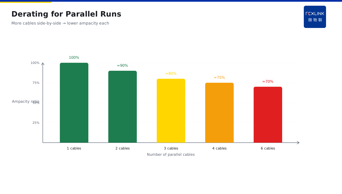
Direct Answer
The owner wants to upgrade a circuit's capacity, but worries about cable overheating — the answer is: cable ampacity is not a fixed number, it is a heat balance result. Ambient temperature, installation method, and multiple cables in a bundle all change how much current you can actually run.
Many factories face this problem: they want to increase capacity on a circuit, but do not know if the cable can handle it. Push more current? Risk overheating. Do not push? Not enough power. Because:
- Cable ampacity is a heat balance: heat generated = I²R, heat dissipated = temperature difference / thermal resistance;
- Ambient temperature correction: hotter environment means worse cooling, lower ampacity;
- Installation affects cooling: conduit, tray, direct burial — cooling conditions are completely different;
- Multicircuit derating: several cables bundled together heat each other, ampacity must be derated.
Key insight: cable ampacity is not a fixed number on the nameplate, it is a heat balance result. You think you can run 300A, but on site you may only be able to run 200A. To know the real margin, you must look at actual cooling conditions.
One factory wanted to increase a production line capacity by 30%. Looking at the cable nameplate ampacity 300A, felt safe. After upgrade, cable temperature shot up to 70°C, insulation aging accelerated. Why? Because the cables were three parallel in conduit, ambient 40°C, actual ampacity much lower than nameplate. If they had calculated the heat balance beforehand, this would not have happened.
1. Cable Radial Thermal Resistance Model
After the cable heats up, how does heat reach the environment?
Radial thermal resistance model:
- Conductor generates heat;
- Heat passes through insulation layer;
- Then through jacket;
- Then to surrounding environment.
Thermal resistance layers:
- Insulation layer thermal resistance;
- Jacket thermal resistance;
- Surrounding environment thermal resistance (soil/air).
Key: cable temperature = ambient temperature + heat generation × total thermal resistance. More heat, more resistance, higher temperature.
2. Heat Generation and Dissipation Balance Equation
How do heat generation and cooling balance?
Heat generation:
- P = I²R;
- Higher current, more heat.
Heat dissipation:
- Q = (T_cable - T_env) / R_th;
- Bigger temperature difference between cable and ambient, faster cooling.
At balance:
- Heat generated = heat dissipated;
- I²R = (T_max - T_env) / R_th;
- Solve for I, that is the ampacity.
Key: ampacity is the current at which heat generation equals cooling. Push more current, cooling cannot keep up, temperature keeps rising, eventually burns the insulation.
3. Why Ambient Temperature Correction Factor
Why correct for ambient temperature?
Because:
- Ampacity is calculated at a base ambient temperature (say 25°C);
- If actual ambient is hotter, the temperature difference is smaller;
- Cooling is worse;
- Ampacity must be derated.
Example:
- Base ambient 25°C, ampacity 300A;
- Actual ambient 40°C, correction factor about 0.85;
- Actual ampacity = 300 × 0.85 = 255A.
Key: hotter ambient, lower ampacity. Do not look at the nameplate number, look at actual ambient correction.
4. Multicircuit Parallel Derating
Why derate when multiple cables are laid together?
Because:
- Single cable: self-heating, surroundings cool it;
- Multiple parallel: they heat each other, surrounding temperature rises;
- Cooling condition gets worse;
- Each cable's ampacity must be derated.
Example:
- Single cable on tray: ampacity 100%;
- Three parallel: derate to about 80%;
- Six parallel: derate to about 70%.
Key: multicircuit parallel, each cable must derate. Do not calculate as single, correct for actual number of cables.
5. Why Capacity Upgrade Needs Measured Temperature Data
Why measure actual temperature for capacity upgrade decisions?
Because:
- Theoretical calculation has many assumptions;
- Actual site cooling conditions may differ from assumptions;
- Measured temperature is the most accurate;
- Measure cable surface temperature directly, you know exactly how much margin left.
Capacity upgrade steps:
- First measure cable temperature at current load;
- Calculate how much more temperature rise allowed before insulation limit;
- Use heat balance equation, reverse-calculate how much more current can be added;
- Then upgrade with confidence.
FEXLINK WB-TM-01/02 wireless temperature node, mounted on cable surface, real-time temperature monitoring. Combined with ESA all-element smart meter current data, you can calculate actual cable ampacity margin.
6. A Real Case
One factory wanted to upgrade a circuit capacity by 20%.
- Theoretical calculation: cable nameplate 250A, currently running 200A, felt margin enough;
- But measured cable surface temperature was already 65°C;
- Calculated: ambient 35°C, insulation limit 90°C, only 25°C rise margin left;
- By heat balance calculation, maximum 10% more, cannot add 20%;
- Finally upgraded only 10%, cable temperature just reached 75°C, safe.
If they had only used nameplate, directly added 20%, the cable might have overheated.
7. Three Common On-Site Mistakes
Mistake 1: only look at nameplate ampacity, no ambient or installation correction. Nameplate is at base conditions, site conditions are different, must correct.
Mistake 2: no derating for multicircuit parallel. Mutual heating, every cable must derate.
Mistake 3: no temperature measurement, pure calculation. Calculation is theoretical, measurement is actual. Must measure to calibrate.
8. One Sentence to Remember
Cable ampacity is a heat balance result: heat = cooling. Hotter ambient, more crowded installation, lower ampacity. Before upgrading capacity, measure temperature, do not just trust the nameplate.
Do not upgrade on a hunch, calculate by heat balance.
9. Common Questions
Q: Cable nameplate says 300A, why can I not actually run 300A? A: Because nameplate is at base conditions (25°C ambient, single cable open installation). Actual site ambient is hotter, installation more crowded, cooling worse, actual ampacity must be derated.
Q: I want to upgrade capacity, how do I know if the cable can handle it? A: Measure cable temperature at current load, see how much margin left to insulation limit, reverse-calculate how much more current can be added by heat balance equation.
10. Why This Is Becoming More Important
As factories get more automated and equipment denser, power demand keeps growing. People want to add more load on existing cables. But cables are thermal machines, not just electrical ones.
Old cables have aged insulation. Their heat resistance is lower than new cables. A new cable rated 300A may only safely run 250A after 15 years of service. You cannot apply new cable standards to old cables.
That is why temperature measurement before upgrade is not conservative — it is safe. You think there is margin, but aging may have eaten it already. Measure the temperature, and you know the real situation.
FEXLINK helps you see the real picture. WB-TM-01/02 measures temperature. ESA measures current. Together, they tell you how much margin your cables really have.
Stay safe. Stay professional. Stay curious.
11. Quick Checklist
Before you upgrade your next circuit, run through this checklist:
- Do you know the actual ambient temperature where the cable runs?
- Do you know how many cables are bundled together?
- Have you measured actual cable temperature under full load?
- Do you know what insulation limit your cable type has?
- Have you corrected the nameplate ampacity for actual site conditions?
If you answered "no" to most of these, your upgrade plan may be riskier than you think. You may be pushing current through a cable that is already running hot. You just have not measured it.
The FEXLINK platform helps you make cable capacity decisions with data. WB-TM-01/02 measures cable temperature. ESA measures current. The platform calculates the real margin. You make the call.
12. How to Build a Cable Monitoring Routine
A good cable monitoring routine starts with the critical circuits. Not every cable needs a sensor. Focus on the ones that carry the most load, the ones that feed critical production, the ones that are about to be upgraded.
Install temperature sensors on those key circuits. Mount them at the joints, the splices, the spots most likely to overheat. Current you can measure at the breaker, but temperature must be measured at the cable itself.
Build a baseline. When the system is new, record what temperature the cable runs at, under what load. That is your normal. Then every month, compare to baseline. See when things start drifting.
Review during summer. The hottest days of the year are when cables run hottest. Check then. If the temperature gets close to insulation limit on the hottest day, you know you cannot add more load.
Start today. Pick your most critical circuit. Measure its temperature. Measure its current. Calculate the margin. Then you know exactly how much room you have.
Final Thoughts
Cable ampacity is one of those things that seems simple, but gets you into trouble if you take it for granted. The nameplate gives you a number. But that number assumes ideal conditions. Real life is never ideal.
Heat balance is the key idea. Cables generate heat when current flows. They cool down when the heat can escape. When generation equals dissipation, that is the limit. Push past it, and temperature keeps climbing.
Do it smart. Do it with measurement. Do it with the heat balance in mind.
Your cables will thank you. Your production line will thank you. Your insurance company will thank you. Stay safe, and keep measuring.
See you in the next article. Take care, and remember: cables run hot when you push them hard — measure before you push.
That is all for this article. Good luck, and stay cable-safe. Until next time.