 微物联研究院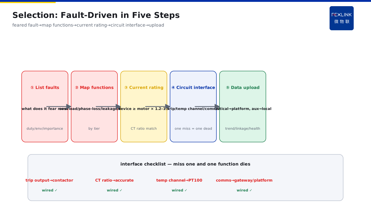
Direct Answer
A workshop's motor circuits are being retrofitted; protection devices come in many models — how do you package overload, phase-loss, leakage, and temperature functions? The answer: configure by motor importance — general auxiliary motors get basic overload + phase-loss protection; critical pumps/fans add leakage and current-unbalance; hot/humid locations add winding-temperature input. When choosing, first list "what fault this motor fears most," then map functions — rather than going straight to the highest model.
At a factory, 30 motors were to be retrofitted: 10 general auxiliaries (exhaust fans, small pumps), 15 critical process pumps/fans, and 5 motors in hot/humid locations (boiler room, pump house). Configuring everything at the top tier wasted money and left most functions idle; configuring everything at the bottom tier left leakage risk unguarded on critical pumps. Tiered by "what they fear most": auxiliaries fear overload burnout — basic overload + phase-loss protection (the ESB Three-Phase Unbalance Monitor also covers current monitoring); critical pumps/fans fear phase-loss burnout and leakage injury — add leakage protection (the ESF Electrical Fire Controller linked) and current-unbalance monitoring; hot/humid motors fear winding overheating — add winding-temperature input (PT100 into the device). Retrofit cost was 30% lower than "top tier everywhere," with no key fault coverage lost.
Because:
- Functions are not "the more the better"; they are "matched to faults": overload prevents burnout, phase-loss prevents single-phase running, leakage prevents injury, temperature prevents overheating — each function guards one fault class;
- Tier by importance: auxiliary faults have small consequences, basic tier; critical pumps have large consequences, add protection; hot/humid environments decide fault probability, add temperature;
- List "what it fears most" first, then choose functions: the motor's duty, environment, and importance define the fault list; the function list follows it;
- Data upload is on demand: critical equipment data reaches the platform (trends, alerts, linkage); general auxiliaries can stay local — not every motor needs the cloud.
Key insight: motor-protection selection is fault-driven, not model-driven. First think what this motor fears most, then map functions — money spent where it matters, protection with no gaps.
At a chemical workshop, a reactor-agitator motor had only overload protection. Once, a phase loss ran 40 minutes; the winding overheated and burned, shutting production for two days. Review: in the "what it fears most" list, this motor feared phase loss (frequent grid fluctuations) and overheating (continuous duty) — phase-loss protection absent, temperature not connected. Rectified: added phase-loss protection (ESB real-time monitoring) and winding-temperature input. Later, a phase loss alarmed and stopped the motor within 20 seconds, preventing another burnout. Ask "what fault it fears most" first, and map functions — one missing item can fail at the worst moment.
1. The Common Function List and the Faults They Cover
Set out the function-to-fault table first:
1. Overload protection (thermal/current overload):
- Prevents: prolonged overload or locked rotor overheating the winding;
- Principle: judges by current-vs-time curve; trips above the allowed value;
- Applies: all motors (basic protection).
2. Phase-loss / open-phase protection:
- Prevents: single-phase running after one phase is lost, abnormal current rise, winding burnout;
- Principle: detects three-phase current unbalance/phase loss, trips immediately;
- Applies: all motors (single-phase running is a top burnout cause).
3. Leakage protection (residual current):
- Prevents: insulation damage leaking to the frame → electric shock/fire;
- Principle: detects residual current; trips/alarms above threshold;
- Applies: critical pumps/fans, humid environments, motors people touch often.
4. Current-unbalance / three-phase unbalance monitoring:
- Prevents: three-phase voltage unbalance, early inter-turn short circuit, wiring issues;
- Principle: monitors phase-current deviation; alarms over limit;
- Applies: critical equipment (early detection of winding/supply issues).
5. Winding-temperature protection (PT100/thermistor):
- Prevents: winding overheating from overload, poor cooling, frequent starts (direct measurement is the most reliable);
- Principle: embedded temperature sensor; trips/alarms over temperature;
- Applies: hot/humid environments, continuous duty, large motors.
Function-to-fault conclusion:
- Overload/phase-loss = the basic pair; every motor should have them;
- Leakage = safety item; add on critical + humid;
- Unbalance = early-warning item; add on critical equipment;
- Temperature = environment item; add on hot/continuous duty.
Key insight: the function list is the mirror of the fault list. Whatever faults this motor has, protect accordingly — no over-spec, no gaps.
2. Three-Tier Configuration
Tier by motor importance and map functions:
Tier 1: general auxiliaries (exhaust fans, small pumps, non-critical conveyors):
- Fault risks: mainly overload, phase loss;
- Configuration: overload + phase-loss (the basic pair);
- Purpose: prevent burnout at the lowest cost;
- Data upload: local protection suffices; no cloud needed.
Tier 2: critical pumps/fans (process pumps, circulation pumps, fire fans):
- Fault risks: phase-loss burnout + leakage injury + early unbalance faults;
- Configuration: overload + phase-loss + leakage + three-phase unbalance monitoring;
- Purpose: prevent burnout + electric shock + early warning;
- Data upload: data to the platform (trends, alert linkage).
Tier 3: hot/humid/continuous-duty motors (boiler room, pump house, reactor):
- Fault risks: overload + overheating (environment-driven) + leakage;
- Configuration: overload + phase-loss + leakage + winding-temperature input;
- Purpose: measure winding temperature directly — the most reliable burnout prevention;
- Data upload: temperature trends to the platform; pre-overheat alerts.
Tier logic:
- Tier 1 "basic burnout prevention"; Tier 2 "burnout + shock + warning"; Tier 3 "environment-specialized (temperature)";
- One motor can combine tiers: a critical pump in a humid location = Tier 2 + temperature = Tier 3 configuration.
Key insight: tiering is by importance × environment, not by motor power. A small but critical pump may need Tier 2 — decide by "what it fears most."
3. Matching Device Rating to Motor Power
Once functions are set, the device rating must match the motor:
Rating-match points:
- Current rating: device rated current ≥ motor rated current (1.2–1.5× margin; starting current is 5–7× but protection sets by rated current);
- CT/sampling: CT ratio chosen by motor rated current so small currents measure accurately (no false unbalance alarms at light load);
- Temperature inputs: PT100/thermistor channel count matches (how many winding points);
- Control circuit: device output contact capacity matches the contactor/breaker trip circuit.
Common mismatches:
- Device too large: small motor with a big device — light-load current below measurement accuracy, protection insensitive;
- Device too small: big motor with a small device — rated current exceeds the range, protection ineffective;
- Missing temperature channels: needs winding temperature but selects a model without temperature inputs.
Match principle:
- First set motor rated current → choose device current rating;
- Then set function needs (phase-loss/leakage/temperature) → choose the function model;
- Finally check control-circuit interfaces (trip contacts, comms port).
Key insight: rating matching is "current → function → interface" in three steps. Power is not the only factor — current range, function channels, and circuit interfaces must all line up.
4. Interfaces with the Existing Distribution Circuit
A retrofit is not finished by swapping the device; check the interfaces early:
Interface list:
- Current circuit: CT secondary into the device (or the device's built-in through-core CT);
- Voltage circuit (if voltage monitoring): taken from the breaker/contactor load side;
- Control circuit: device trip output to the contactor/breaker (replacing the original thermal-relay position);
- Temperature circuit: winding PT100/thermistor into the device's temperature channels;
- Comms: RS485/Ethernet/wireless to the platform or gateway.
Retrofit points:
- Original thermal-relay position → replace with the monitoring device (check dimensions and mounting);
- CT already present → verify ratio and accuracy; absent → add a through-core CT (live install? confirm on site);
- The trip circuit must "trip independently": reliably open the contactor on device failure;
- Pre-lay comms cable: run wiring during the retrofit if upload is planned.
Interfaces often overlooked:
- Device installed but trip output not connected: protection is a dummy;
- CT ratio mismatch: displayed current 10× off;
- Temperature sensor not seated: temperature function idle.
Key insight: the interface decides whether protection actually operates. Trip output, CT, temperature channels, comms — miss one and one function fails.
5. Is Data Upload Necessary?
Upload or not, decide by equipment importance:
Recommended to upload (Tier 2, 3):
- Critical pumps/fans: current, unbalance, leakage, temperature trends to the platform;
- Value: trend warning (unbalance creeping = early winding issue), alert linkage (correlated with other distribution alerts), health scoring (motor becomes a deduction item);
- Path: device comms → gateway (e.g., ESX Edge Computing Gateway) → supervision platform.
No need to upload (Tier 1 auxiliaries):
- Local overload/phase-loss tripping is enough;
- Value: protection done locally, less cloud cost;
- Exception: batches of auxiliaries can also report at low cost (unified management when large in number).
Upload value judgment:
- Large failure consequences, need trend warning → upload;
- Local protection suffices, small consequences → no upload;
- Unified management (many motors centrally monitored) → low-cost batch upload.
Key insight: upload is decided by "do we need trends and linkage." Critical equipment uploads for early warning; auxiliaries stay local — cloud on demand, no waste.
6. Product Landing: Tiered Motor Protection
FEXLINK's ESB Three-Phase Unbalance Monitor and ESF Electrical Fire Controller bring tiered protection to practice:
- ESB Three-Phase Unbalance Monitor: overload + phase-loss + three-phase unbalance monitoring — covers Tier 1's basic pair and Tier 2's unbalance warning;
- ESF Electrical Fire Controller: residual-current (leakage) monitoring + linkage — covers Tier 2's leakage protection;
- Winding-temperature input: PT100 into the monitoring device — covers Tier 3 temperature;
- Device comms to ESX Edge Computing Gateway → Digital Electrical Intelligent Supervision System: unified trends, alerts, health;
- Tiered configuration by "what fault it fears most": auxiliary basic tier, critical-pump safety tier, hot-motor temperature tier.
Design principle in one sentence: turn "model selection" into "fault-list mapping." List the feared faults first, then configure functions — protection in place, no wasted money.
7. Common On-Site Mistakes
- Straight to the top model: all motors get the highest tier. Consequence: money wasted, functions idle. Correct: tier by importance; the fault list sets functions.
- Overload only, no phase-loss: phase loss is a top burnout cause. Consequence: single-phase running burns the motor. Correct: overload + phase-loss is the basic pair.
- No leakage in humid environments: shock risk. Consequence: live frame with no protection. Correct: add leakage on critical + humid.
- Needs temperature but picks a model without temperature inputs: function and hardware mismatch. Consequence: temperature function idle. Correct: functions first, then the model.
- Device installed, trip not connected: protection does not act. Consequence: protection fails at the fault. Correct: check interfaces item by item (trip output, CT, temperature channels, comms).
Scope and Limitations
This article discusses packaging motor protection functions (overload/phase-loss/leakage/unbalance/temperature) and tiered selection of motor protection devices for workshop circuit retrofits and new builds. Tiering and function suggestions are engineering experience references; actual choices follow motor duty, environment, importance, and vendor products. Device current ratings must match motor rated current; interface retrofits must follow site circuits and safety procedures. Data upload is decided by equipment importance and needs unified platform integration to form trend warnings. All cases are anonymized (a certain factory / chemical workshop) and do not refer to any specific customer.