 微物联研究院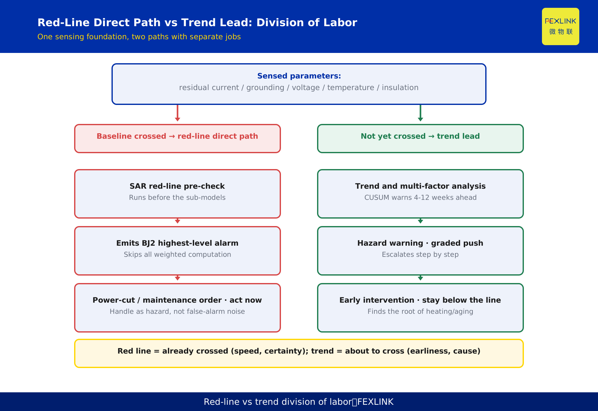
Direct Answer
The non-negotiable red-line thresholds in the system are not arbitrary choices made by the product team — they are national-standard baselines moved to the front line: residual current ≥300 mA maps to GB 13955, abnormal (open-circuit) grounding resistance maps to GB 50057, three-phase voltage unbalance >15% maps to GB/T 15543, line temperature ≥110°C maps to GB 16895, and insulation resistance <0.5 MΩ maps to GB/T 16895. Together these five red lines form the "SAR red-line guard": they are evaluated before any analytical model runs, and when triggered they directly emit the highest-level alarm, skipping all weighted computation — the national-standard baseline is never crossed.
Why Red Lines Exist: National Baselines Moved to the Front
"Red lines" and "ordinary alarms" are fundamentally different. Ordinary alarms run complex calculations — multi-factor weighting, trend analysis, scenario recognition — and conclude "possibly problematic." Red lines mean "the national-standard baseline has already been crossed" and conclude "act immediately." Their different status dictates different handling: the red-line pre-check runs before the Qianzhi sub-models, and on trigger directly emits the highest-level alarm (BJ2), skipping all weighted computation. The engineering rationale: intermediate steps of weighted computation can introduce deviation, and a national-standard baseline permits none — so red lines bypass the computation path entirely and take a direct path.
Where do the thresholds come from? National standards. China's electrical-safety and power-quality standards include mandatory and recommended national standards that specify limits for residual current, grounding, voltage unbalance, temperature, insulation, and other parameters. Turning these clauses directly into system thresholds has three benefits: traceable — anyone questioning a threshold can trace it clause by clause to the standard, with no "why this number" black box; principled — national limits are the industry's agreed safety baseline, and aligning red lines with them means the safety baseline never relaxes regardless of site conditions; tamper-proof — once fixed, no one can raise a red-line threshold, preventing sites from loosening the baseline to reduce alarm noise.
SAR-01 Residual Current ≥300 mA and GB 13955
Threshold: residual current ≥300 mA; basis: GB 13955, "Installation and Operation of Residual Current Operated Protective Devices."
GB 13955 is the mandatory national standard for residual-current (earth-leakage) protection, covering installation, operation, and maintenance of residual-current devices. 300 mA is the critical level: it is the dividing point between personal safety and equipment safety. Below 300 mA, residual current is mostly background — slight insulation degradation, distributed line capacitance — and can be caught early by trend monitoring. At 300 mA and above, insulation is clearly broken: leakage can cause electric shock or arcing-fire risk and must be handled immediately.
In the system, SAR-01 triggering means "leakage has entered the danger zone." Unlike ordinary leakage alarms, the red-line action is top priority: it directly pushes a BJ2 alarm and triggers power-cut or maintenance work orders, with no weighted computation in between. For operators, a red-line alarm is a hazard to be handled, not a possible false positive to be investigated first.
SAR-02 Abnormal Grounding Resistance and GB 50057
Threshold: abnormal (open-circuit) grounding resistance; basis: GB 50057, "Code for Design Protection of Structures against Lightning."
GB 50057 is the foundational standard for building lightning-protection design, with clear requirements for grounding resistance. The grounding system safely dissipates lightning and fault currents into the earth; once grounding resistance goes abnormal or open-circuit, the dissipation path fails, and under lightning or fault the voltage strikes back along the conductors, threatening equipment and people. GB 50057 grades grounding-resistance requirements by building class; the system's "open-circuit abnormal grounding" red line maps to the most severe case — the grounding path has materially failed.
Note the division of labor: the red line captures a deterministic failure ("open-circuit level"); slow degradation of grounding resistance (from acceptable to marginal) belongs to the trend domain, tracked by ordinary alarm paths. The reason is simple: open circuit is an immediate threat needing a red-line direct path; degradation is a gradual risk best handled early by trend analysis. Together they give grounding safety both a floor and an early warning.
SAR-03 Three-Phase Voltage Unbalance >15% and GB/T 15543
Threshold: three-phase voltage unbalance >15%; basis: GB/T 15543, "Power Quality — Three-Phase Voltage Unbalance."
GB/T 15543 sets limits for three-phase voltage unbalance at public coupling points: generally no more than 2% under normal conditions and no more than 4% short-term. Why does the system red line sit at 15%? Because the two observe different things — GB/T 15543 targets supply-quality indicators at the public grid; the red line targets the equipment-safety boundary on the load side. 15% is the magnitude at which equipment can no longer run properly: under severe phase asymmetry, motor negative-sequence current surges and heating increases, electronic rectifiers misbehave, and transformers can overheat locally.
So this red line is not a literal copy of the standard limit but "an equipment-safety baseline within the national-standard system." The 2%/4% coupling-point limits judge supply quality; the on-site 15% red line protects equipment; unbalance below 15% goes to ordinary alarms and trend analysis, while 15% means the equipment tolerance boundary has been crossed and the supply circuit and load distribution must be checked immediately.
SAR-04 Line Temperature ≥110°C and GB 16895
Threshold: line temperature ≥110°C; basis: GB 16895 series, "Electrical Installations of Buildings."
The GB 16895 series (aligned with IEC 60364) is the foundational standard system for the design and safety of building electrical installations, including limits on conductor ampacity and operating temperature. Rising temperature in normal operation accelerates insulation aging; beyond the allowable temperature, insulation life shortens sharply and electrical fire becomes possible. 110°C corresponds to "conductor insulation has crossed its tolerance boundary" — at this temperature conventional PVC/XLPE insulation has visibly degraded and continued operation means a real fire risk.
The value of the temperature red line is that it directly reflects "heat," the physical quantity closest to fire. The electrical-fire chain is: overload or poor contact → temperature rise → insulation degradation → ignition. The temperature red line cuts the chain where "temperature rise has lost control," while the early stage of temperature rise (from normal toward the red line) is tracked by temperature trend analysis to catch growing contact resistance and overload at the source. Red line as the floor, trend as the lead — the basic pairing of temperature safety management.
SAR-05 Insulation Resistance <0.5 MΩ and GB/T 16895
Threshold: insulation resistance <0.5 MΩ; basis: GB/T 16895 series.
Insulation resistance is the basic indicator of insulation condition in equipment and circuits. The GB/T 16895 series specifies minimum allowable insulation resistance by circuit type; 0.5 MΩ is the fundamental floor for low-voltage circuits. Below this value, insulation has severely degraded, and leakage, short-circuit, and electric-shock risks rise together — continued operation is unsafe.
Like the temperature red line, this one floors the point where "insulation has materially failed"; slow decline (from hundreds of MΩ down to a few MΩ) is caught early by trend and residual-current analysis — for example, S-02 residual-current trend drift (CUSUM) can warn of an insulation-degradation direction 4–12 weeks in advance. The red line is the last gate; trend is the lead time. The two work on different time scales so that safety is both "held" and "early."
How the Five Red Lines Work in the System
The five red lines are not five isolated checks but one unified front-end mechanism:
Positioned first. The red-line pre-check runs before the Qianzhi sub-models — after data ingestion and cleaning, red lines are evaluated first, then the analytical models. This guarantees red-line judgments never depend on intermediate computed results and always speak from raw parameters.
Highest-level response. A red-line trigger directly emits the highest-level alarm (BJ2). Unlike ordinary alarms with graded push and step-by-step escalation, red-line alarms reach handling immediately.
Thresholds cannot be raised. Once fixed, no one can raise a red-line threshold — preventing sites from loosening the baseline because alarms are frequent. Changing a threshold is a process matter, not a UI setting.
Division of labor with ordinary alarms. Red lines govern "baseline already crossed"; ordinary alarms and trend analysis govern "about to cross." The former prioritizes speed and certainty, the latter earliness and root cause — two paths sharing one sensing foundation, each with its own job.
Beyond the Red Lines: How Other Standards Participate
Red lines are only part of the standards system. SAR covers 13 major standards including GB/T 12325, GB/T 14549, and GB/T 15543; further out, the standard service embeds a 408-clause standard library across 12 systems (GB, GB/T, DL, IEC, UL, and more), automatically matching relevant clauses and pushing them with each alarm. The complete safety grading is: red lines (national baselines, direct handling) → standard validation (clause auto-matching, supporting handling basis) → weighted analysis (trend and scenario recognition, early warning). Understanding this grading lets you locate any alarm in the system — which level it is, what it is based on, and how strongly to respond.
Scope and Limitations
The five red-line thresholds described in this article (SAR-01 residual current ≥300 mA, SAR-02 abnormal open-circuit grounding resistance, SAR-03 three-phase voltage unbalance >15%, SAR-04 line temperature ≥110°C, SAR-05 insulation resistance <0.5 MΩ) and their national-standard sources (GB 13955, GB 50057, GB/T 15543, GB 16895, GB/T 16895) come from the FEXLINK product knowledge base (Taiyi central-control system SAR red-line guard) and were cross-checked against the relevant national-standard clauses. Statements such as "red lines directly emit BJ2 highest-level alarms," "thresholds cannot be raised," and "408-clause standard library / 12 systems" represent product-capability documentation. National-standard limits should follow the currently effective versions; special premises (explosive atmospheres, medical facilities, special processes) have stricter requirements per the applicable codes. Handling triggered by red lines (power cut, maintenance) must be carried out by qualified professionals based on site conditions. Example scenarios are anonymized illustrations and do not refer to any specific customer.