 微物联研究院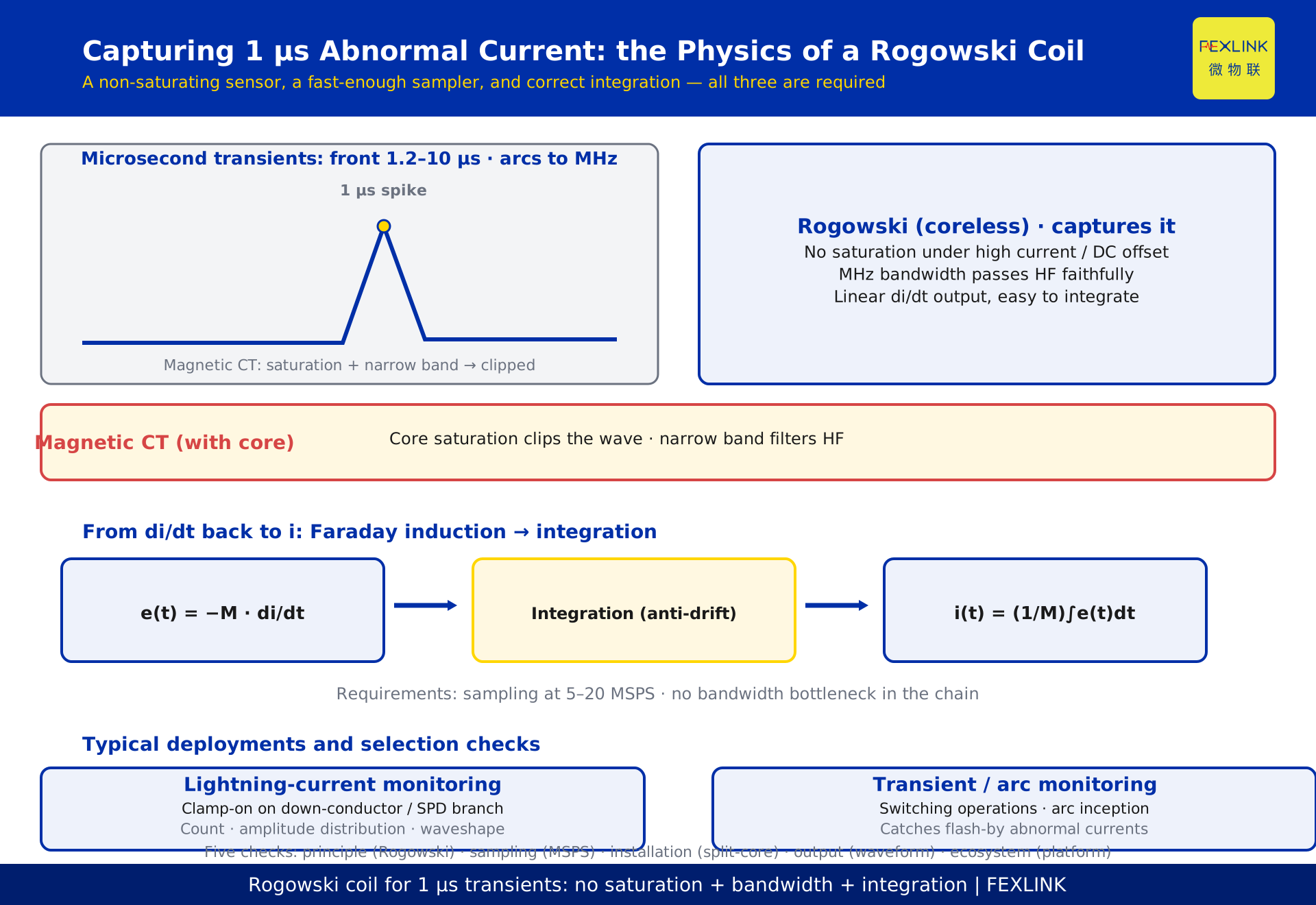
Direct Answer
Lightning surges, fault arcs, and switching transients produce abnormal currents that last only microseconds — often less than 1 μs from onset to disappearance. Why can an ordinary current transformer (CT) not capture them? Two physical limits: core saturation and insufficient bandwidth. A board-mounted Rogowski coil takes a different path: it measures the rate of change of current (di/dt) via Faraday induction, has no magnetic core, cannot saturate, and offers very high bandwidth. Combined with high-speed sampling and an integrator that reconstructs the waveform, it captures microsecond transients without breaking the circuit. In one sentence: a device that can really see 1 μs transients earns that ability not from a "more sensitive transformer" but from the combination of a non-saturating sensor, a fast-enough sampler, and a correct reconstruction algorithm.
1. What a 1 μs Abnormal Current Actually Means
First, build an intuition for the time scale. One 50 Hz power cycle lasts 20 ms; one microsecond is one twenty-thousandth of that. The front time of a lightning current (from zero to peak) is typically 1.2–10 μs, and the high-frequency components of a fault arc can reach hundreds of kilohertz or even megahertz. In other words, the information that is most useful and most revealing about these events lives entirely in the microsecond range.
For a measurement system this means two things: the sampling rate must be high enough (reconstructing a 1 μs pulse requires at least several MSPS), and the sensor's frequency response must cover that band (if the sensor attenuates high frequencies, the signal is already distorted before it reaches the ADC). Missing either condition, microsecond transients are simply invisible.
2. Why an Ordinary CT Cannot See Them
The conventional magnetic CT is the most familiar current sensor, but it fails on two counts for transients:
First, core saturation. A CT relies on its magnetic core to concentrate flux and induce the secondary signal, and the core can handle only so much flux. Transients are often large in amplitude and may carry DC offset, which easily drives the core into saturation. Once saturated, the secondary waveform distorts or clips — amplitude and shape become unreliable.
Second, bandwidth limits. The CT's equivalent circuit contains distributed capacitance and leakage inductance that filter out high frequencies. With many secondary turns and significant parasitic parameters, the usable bandwidth is typically a few hundred kilohertz; megahertz components are heavily attenuated. The result: after passing through a CT, a microsecond pulse becomes a "slow, dull" lump — the 1 μs detail is gone.
So the ordinary CT is not "not precise enough"; it does not operate in this frequency band at all.
3. The Rogowski Coil: Faraday Induction and di/dt
The Rogowski coil also works by electromagnetic induction, but with a fundamentally different structure: a wire wound uniformly on a non-magnetic former, forming a loop that encircles the conductor under test. Because the former has no magnetic core, the induced voltage is proportional to the rate of change of the current:
e(t) = −M · di/dt
where M is the mutual inductance. In other words, a Rogowski coil inherently measures "how fast the current is changing," not "how large the current is."
The absence of a core brings three direct benefits:
- No saturation: large currents, DC bias, and transient surges cannot push the sensor into saturation; the range is practically unlimited;
- High bandwidth: no hysteresis and no high-frequency core losses mean a wide frequency response — megahertz components pass faithfully;
- Linear output: M is constant, so the output is strictly linear with di/dt, making accurate reconstruction straightforward.
4. Integration: Reconstructing Current from di/dt
A Rogowski coil outputs a rate of change, but engineers usually need the current waveform itself, so the backend must include an integrator to recover i from di/dt:
i(t) = (1/M) · ∫e(t)dt
This step looks trivial but is the easiest place in the chain to go wrong. First, integrators suffer from offset and temperature drift, accumulating error over long runs. Second, the integrator's low-frequency behavior defines the lower cutoff — with too-low a corner or any DC content, the result drifts. Mature designs therefore balance "preserving high-frequency transient information" against "suppressing integration drift," typically using an analog integrator with high-pass/low-pass shaping plus digital calibration.
The quality of the integration determines whether you measure a genuine transient waveform or a drift-polluted approximation.
5. "Board-Mounted, Odd-Shaped": Split-Core Installation and Immunity
Two properties make Rogowski coils a favorite in the field: split-core (openable) and flexible.
A conventional CT requires disassembling the busbar to thread the conductor through; a Rogowski coil can be built as a split-core design that clamps directly onto an already-running busbar, cable, or lightning down-conductor — installation without de-energizing. For lightning-protection monitoring, which is largely about retrofitting existing assets, this is a decisive advantage.
"Board-mounted, odd-shaped" describes another form: the coil is built directly into the monitoring module's PCB structure with fixed coupling to the conductor under test. The benefits are consistency (controlled assembly tolerance, stable mutual inductance) and immunity (the coil and circuit share one shield, suppressing external magnetic interference) — ideal for mass deployment in switchgear cabinets and SPD branches.
6. Rogowski vs. Conventional CT: One Table, Clear Choice
Placing the two sensors side by side makes the selection logic obvious:
| Dimension | Magnetic CT | Rogowski coil |
|---|---|---|
| Measures | Current i (RMS / instantaneous) | Rate of change di/dt |
| Core | Yes — saturates under large current | Coreless — no saturation |
| Bandwidth | Typically below a few hundred kHz | Up to the MHz range |
| Installation | Needs de-energized threading | Split-core or board-mounted, live |
| Linear range | Limited by the core | Practically unlimited |
| Back end | Direct current output | Requires integration |
| Typical use | Metering, protection, routine monitoring | Lightning, transient, arc monitoring |
One key conclusion follows: the conventional CT is for "accurate readings of normal quantities"; the Rogowski coil is for "catching abnormal quantities." They are complements, not substitutes. Lightning and transient monitoring favors the coil precisely because those signals are wide in amplitude, high in frequency, and demand live installation — exactly the CT's three weak points.
7. Sampling and Bandwidth Needed for 1 μs Response
Turning "the sensor can measure" into "the system can report" requires matching sampling and bandwidth. By the Nyquist criterion, reconstructing the narrowest 1 μs-class pulse needs a sampling rate of at least several MSPS; for waveform detail and rise-time fidelity, engineering practice keeps a 3–5× margin, i.e. 5–20 MSPS.
Every stage of the signal chain must avoid becoming the bottleneck: sensor (Rogowski high-frequency response) → integrator/amplifier (bandwidth vs. drift) → ADC front end (anti-aliasing filter) → sampling. If any stage is too narrow-band, the whole 1 μs capability collapses.
A practical test: check the device's stated sampling rate and bandwidth, then ask "what is the narrowest pulse width it can resolve." If the stated sampling rate is tens of kSPS, or the spec mentions "response speed" without bandwidth, the device almost certainly cannot measure microsecond transients.
8. Where Rogowski Monitoring Lands: Lightning and Transient Scenes
Rogowski monitoring has two common deployments: lightning-current monitoring and transient/arc-current monitoring.
In intelligent lightning protection, the lightning current discharges along the down-conductor — steep front, large amplitude, short duration — exactly the Rogowski coil's home turf. It needs no disconnection of the down-conductor: clamp-on installation measures amplitude and waveshape, and the monitoring system records strike count, amplitude distribution, and time, supporting SPD degradation assessment and equipment life management. FEXLINK's FL lightning/transient current monitor uses a board-mounted Rogowski architecture, deployed on SPD branches and down-conductors, feeding lightning and transient data into the intelligent lightning-protection online monitoring system.
In transient monitoring, switching operations and arc inception produce μs-class current spikes; the coil's wide bandwidth lets these "flash-by" anomalies be recorded as raw evidence for hazard analysis.
9. How to Tell Whether a Device Really Captures 1 μs
A practical checklist:
- Check the sensor principle: an explicit "Rogowski coil / coreless" design inherently has no-saturation and high-frequency foundations; a device that only says "transformer" needs follow-up questions on bandwidth and saturation;
- Check the sampling rate: for 1 μs-class transients, expect at least MSPS;
- Check the installation method: split-core or board-mounted structure determines whether it can be deployed on existing assets;
- Check the output: does it produce "transient waveform / lightning amplitude" results, or only a threshold alarm;
- Check the ecosystem: does the measurement flow into a monitoring platform to form trends and logs, rather than a one-off reading.
In one example, a substation's lightning-protection retrofit added Rogowski monitoring to 12 SPD branches. Within six months, the system recorded more than 30 lightning-current events, two of which exceeded 70% of the SPD's stated discharge capability; SPD configuration was adjusted accordingly. Under the old approach — annual manual inspection of fault indicators — those two SPDs' degradation risk would not have surfaced until the indicators flipped.
Scope and Limitations
The Rogowski principle and sampling configuration discussed here apply to selection and technical judgment for microsecond transient current monitoring; specific sampling rate, bandwidth, and accuracy figures are subject to product documentation. "1 μs-class capture" refers to the sensor-and-sampling chain's ability to resolve the narrowest pulse; it does not mean every anomaly can be identified and alarmed within 1 μs — identification also depends on backend algorithms and threshold settings. The "substation lightning-protection retrofit" case is a desensitized example and does not refer to any specific customer; lightning-amplitude statistics follow the monitoring system's records.